Product Description
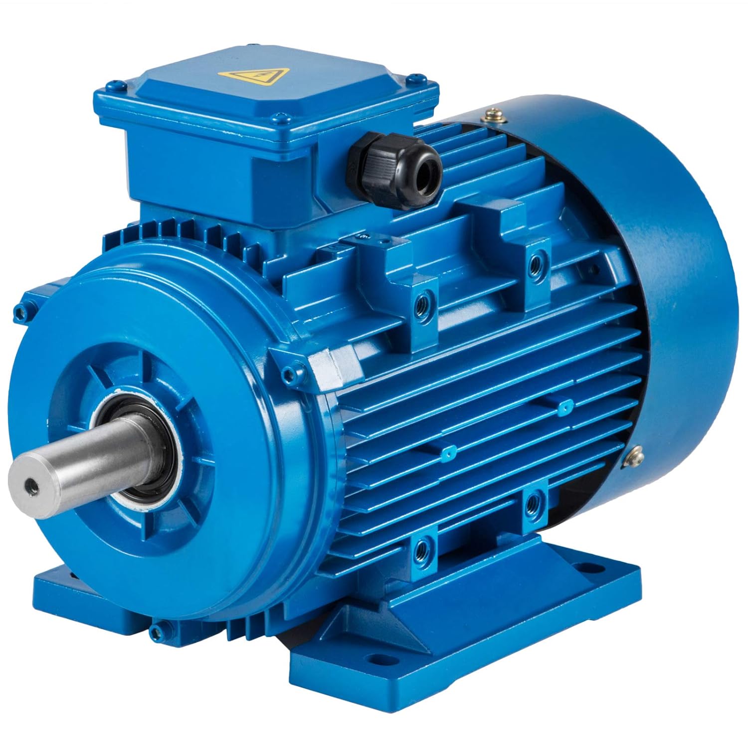
0.55kw 0.75kw 3-phase AC gear motor
Motor Specifications
Motor Parameters
| Ratio | Output speed | Output torque | ||||||||||||||||||
| 1/8 HP | 1/4 HP | 1/2 HP | 3/4 HP | 1 HP | 3/2 HP | 2HP | 3HP | 5HP | ||||||||||||
| 0.1KW | 0.2KW | 0.4KW | 0.55KW | 0.75KW | 1.1KW | 1.5KW | 2.2KW | 3.7KW | ||||||||||||
| Hz | ||||||||||||||||||||
| 50 | 60 | 50 | 60 | 50 | 60 | 50 | 60 | 50 | 60 | 50 | 60 | 50 | 60 | 50 | 60 | 50 | 60 | 50 | 60 | |
| 3 | 500 | 600 | 0.19 | 0.16 | 0.37 | 0.31 | 0.70 | 0.60 | 0.96 | 0.83 | 1.30 | 1.10 | 1.91 | 1.61 | 2.60 | 2.20 | 3.80 | 3.20 | 6.00 | 5.50 |
| 5 | 300 | 360 | 0.31 | 0.26 | 0.62 | 0.52 | 1.20 | 1.00 | 1.65 | 1.38 | 2.20 | 1.90 | 3.22 | 2.78 | 4.50 | 3.80 | 6.72 | 5.60 | 11.0 | 10.0 |
| 10 | 150 | 180 | 0.62 | 0.52 | 1.24 | 1.04 | 2.40 | 2.00 | 3.30 | 2.75 | 4.50 | 3.80 | 6.60 | 5.7 | 9.10 | 7.60 | 13.7 | 11.2 | 22.0 | 20.0 |
| 15 | 100 | 120 | 0.91 | 0.76 | 1.80 | 1.50 | 3.60 | 3.00 | 4.95 | 4.13 | 6.80 | 5.70 | 9.70 | 8.36 | 13.5 | 11.3 | 20.1 | 16.8 | 32.6 | 29.8 |
| 20 | 75 | 90 | 1.20 | 1.00 | 2.40 | 2.00 | 4.80 | 4.00 | 6.60 | 5.50 | 9.00 | 7.50 | 13.20 | 11.0 | 18.1 | 15.1 | 26.8 | 22.4 | 43.6 | 36.0 |
| 25 | 60 | 72 | 1.40 | 1.20 | 3.00 | 2.50 | 6.00 | 5.00 | 8.25 | 6.88 | 11.2 | 9.40 | 16.43 | 13.79 | 22.6 | 18.9 | 33.6 | 28.0 | 53.9 | 49.53 |
| 30 | 50 | 60 | 1.80 | 1.50 | 3.60 | 3.00 | 7.20 | 6.00 | 9.90 | 8.25 | 13.5 | 11.3 | 19.80 | 16.57 | 27.1 | 22.6 | 40.3 | 33.6 | 64.7 | 58.8 |
| 40 | 37 | 45 | 2.20 | 1.90 | 4.60 | 3.90 | 9.30 | 7.80 | 12.79 | 10.73 | 17.5 | 14.6 | 25.66 | 21.41 | 34.9 | 29.1 | 52.0 | 43.4 | 86.3 | 78.4 |
| 45 | 33 | 40 | 2.70 | 2.20 | 5.40 | 4.40 | 10.9 | 9.10 | 14.99 | 12.51 | 20.6 | 17.0 | 30.21 | 24.93 | 41.1 | 34.0 | 59.8 | 49.6 | 98.5 | 81.7 |
| 50 | 30 | 36 | 2.80 | 2.40 | 5.70 | 4.80 | 11.6 | 9.70 | 15.95 | 13.34 | 21.9 | 18.3 | 32.12 | 26.84 | 43.6 | 36.4 | 65.1 | 54.3 | 107 | 97.0 |
| 60 | 25 | 30 | 3.40 | 2.90 | 6.90 | 5.80 | 13.9 | 11.6 | 19.11 | 15.95 | 26.2 | 21.9 | 38.43 | 30.21 | 52.4 | 43.7 | 78.1 | 65.1 | 127 | 115 |
| 70 | 21 | 25 | 4.30 | 3.60 | 8.00 | 6.80 | 16.2 | 13.5 | 22.28 | 18.56 | 31.5 | 26.3 | 46.20 | 38.57 | 62.4 | 52.0 | 92.5 | 77.1 | ||
| 80 | 19 | 23 | 4.80 | 4.00 | 9.20 | 7.70 | 18.4 | 15.4 | 25.30 | 21.18 | 35.5 | 29.6 | 52.07 | 43.41 | 70.8 | 59.0 | 105 | 87.5 | ||
| 90 | 17 | 20 | 5.20 | 4.40 | 10.3 | 8.60 | 20.7 | 17.3 | 28.46 | 23.79 | 39.3 | 32.8 | 57.64 | 48.10 | 77.1 | 64.3 | 113 | 94.3 | ||
| 100 | 15 | 18 | 5.80 | 4.90 | 11.5 | 9.60 | 23.0 | 19.2 | 31.63 | 26.40 | 43.2 | 36.0 | 63.36 | 52.8 | 83.7 | 69.8 | 126 | 105 | ||
| 120 | 12 | 15 | 6.90 | 5.80 | 13.8 | 11.5 | 27.7 | 23.1 | 38.09 | 31.76 | 51.8 | 43.2 | 75.97 | 63.36 | 101 | 83.7 | ||||
| 140 | 11 | 13 | 8.00 | 6.70 | 16.0 | 13.4 | 32.0 | 26.7 | 44.0 | 36.71 | 59.7 | 49.8 | 87.56 | 73.04 | 116 | 96.8 | ||||
| 160 | 9 | 11 | 9.10 | 7.60 | 18.3 | 15.3 | 36.3 | 30.3 | 49.91 | 41.66 | 68.0 | 56.7 | 99.73 | 83.16 | 132 | 110 | ||||
| 180 | 8 | 10 | 10.3 | 8.60 | 20.7 | 17.3 | 40.8 | 34.0 | 56.10 | 46.78 | 76.8 | 64.0 | 112.6 | 93.87 | 148 | 123 | ||||
| 200 | 7 | 9 | 11.6 | 9.70 | 22.9 | 19.1 | 43.2 | 36.0 | 59.40 | 49.5 | 82.8 | 69.0 | ||||||||
Note:
We only show several motor models, if these models are not what you want, please freely tell us about your requirement. We will provide you with a suitable motor solution and price soon.
FAQ
1 Q: What’s your MOQ?
A: 1unit is ok for different types.
2 Q: What about your warranty?
A: One year.
3 Q: Do you provide OEM service with customer-logo?
A: Yes, we could do OEM orders, but we mainly focus on our own brand.
4 Q: How about your payment terms ?
A: TT, western union and paypal. 100% payment in advanced for orders less $5,000. 30% deposit and balance before delivery for orders over $5,000.
5 Q: How about your packing ?
A: Carton, Plywood case. If you need more, we can pack all goods with pallet
6 Q: What information should be given, if I buy from you ?
A: Rated power, gearbox ratio, input speed, mounting position. More details, better!
7 Q: How do you deliver the order?
A: We will compare and choose the most suitable ways of delivery by sea, air or express courier.
Warmly welcome your inquiries !
/* January 22, 2571 19:08:37 */!function(){function s(e,r){var a,o={};try{e&&e.split(“,”).forEach(function(e,t){e&&(a=e.match(/(.*?):(.*)$/))&&1
| Application: | Industrial |
|---|---|
| Speed: | High Speed |
| Number of Stator: | Three-Phase |
| Function: | Driving, Control |
| Casing Protection: | Protection Type |
| Number of Poles: | 4 |
| Samples: |
US$ 50/Piece
1 Piece(Min.Order) | |
|---|
| Customization: |
Available
|
|
|---|

What types of feedback mechanisms are commonly integrated into gear motors for control?
Gear motors often incorporate feedback mechanisms to provide control and improve their performance. These feedback mechanisms enable the motor to monitor and adjust its operation based on various parameters. Here are some commonly integrated feedback mechanisms in gear motors:
1. Encoder Feedback:
An encoder is a device that provides position and speed feedback by converting the motor’s mechanical motion into electrical signals. Encoders commonly used in gear motors include:
- Incremental Encoders: These encoders provide information about the motor’s shaft position and speed relative to a reference point. They generate pulses as the motor rotates, allowing precise measurement of position and speed changes.
- Absolute Encoders: Absolute encoders provide the precise position of the motor’s shaft within a full revolution. They do not require a reference point and provide accurate feedback even after power loss or motor restart.
2. Hall Effect Sensors:
Hall effect sensors use the principle of the Hall effect to detect the presence and strength of a magnetic field. They are commonly used in gear motors for speed and position sensing. Hall effect sensors provide feedback by detecting changes in the motor’s magnetic field and converting them into electrical signals.
3. Current Sensors:
Current sensors monitor the electrical current flowing through the motor’s windings. By measuring the current, these sensors provide feedback regarding the motor’s torque, load conditions, and power consumption. Current sensors are essential for motor control strategies such as current limiting, overcurrent protection, and closed-loop control.
4. Temperature Sensors:
Temperature sensors are integrated into gear motors to monitor the motor’s temperature. They provide feedback on the motor’s thermal conditions, allowing the control system to adjust the motor’s operation to prevent overheating. Temperature sensors are crucial for ensuring the motor’s reliability and preventing damage due to excessive heat.
5. Hall Effect Limit Switches:
Hall effect limit switches are used to detect the presence or absence of a magnetic field within a specific range. They are commonly employed as end-of-travel or limit switches in gear motors. Hall effect limit switches provide feedback to the control system, indicating when the motor has reached a specific position or when it has moved beyond the allowed range.
6. Resolver Feedback:
A resolver is an electromagnetic device used to determine the position and speed of a rotating shaft. It provides feedback by generating sine and cosine signals that correspond to the shaft’s angular position. Resolver feedback is commonly used in high-performance gear motors requiring accurate position and speed control.
These feedback mechanisms, when integrated into gear motors, enable precise control, monitoring, and adjustment of various motor parameters. By utilizing feedback signals from encoders, Hall effect sensors, current sensors, temperature sensors, limit switches, or resolvers, the control system can optimize the motor’s performance, ensure accurate positioning, maintain speed control, and protect the motor from excessive loads or overheating.

What is the significance of gear reduction in gear motors, and how does it affect efficiency?
Gear reduction plays a significant role in gear motors as it enables the motor to deliver higher torque while reducing the output speed. This feature has several important implications for gear motors, including enhanced power transmission, improved control, and potential trade-offs in terms of efficiency. Here’s a detailed explanation of the significance of gear reduction in gear motors and its effect on efficiency:
Significance of Gear Reduction:
1. Increased Torque: Gear reduction allows gear motors to generate higher torque output compared to a motor without gears. By reducing the rotational speed at the output shaft, gear reduction increases the mechanical advantage of the system. This increased torque is beneficial in applications that require high torque to overcome resistance, such as lifting heavy loads or driving machinery with high inertia.
2. Improved Control: Gear reduction enhances the control and precision of gear motors. By reducing the speed, gear reduction allows for finer control over the motor’s rotational movement. This is particularly important in applications that require precise positioning or accurate speed control. The gear reduction mechanism enables gear motors to achieve smoother and more controlled movements, reducing the risk of overshooting or undershooting the desired position.
3. Load Matching: Gear reduction helps match the motor’s power characteristics to the load requirements. Different applications have varying torque and speed requirements. Gear reduction allows the gear motor to achieve a better match between the motor’s power output and the specific requirements of the load. It enables the motor to operate closer to its peak efficiency by optimizing the torque-speed trade-off.
Effect on Efficiency:
While gear reduction offers several advantages, it can also affect the efficiency of gear motors. Here’s how gear reduction impacts efficiency:
1. Mechanical Efficiency: The gear reduction process introduces mechanical components such as gears, bearings, and lubrication systems. These components introduce additional friction and mechanical losses into the system. As a result, some energy is lost in the form of heat during the gear reduction process. The efficiency of the gear motor is influenced by the quality of the gears, the lubrication used, and the overall design of the gear system. Well-designed and properly maintained gear systems can minimize these losses and optimize mechanical efficiency.
2. System Efficiency: Gear reduction affects the overall system efficiency by impacting the motor’s electrical efficiency. In gear motors, the motor typically operates at higher speeds and lower torques compared to a direct-drive motor. The overall system efficiency takes into account both the electrical efficiency of the motor and the mechanical efficiency of the gear system. While gear reduction can increase the torque output, it also introduces additional losses due to increased mechanical complexity. Therefore, the overall system efficiency may be lower compared to a direct-drive motor for certain applications.
It’s important to note that the efficiency of gear motors is influenced by various factors beyond gear reduction, such as motor design, control systems, and operating conditions. The selection of high-quality gears, proper lubrication, and regular maintenance can help minimize losses and improve efficiency. Additionally, advancements in gear technology, such as the use of precision gears and improved lubricants, can contribute to higher overall efficiency in gear motors.
In summary, gear reduction is significant in gear motors as it provides increased torque, improved control, and better load matching. However, gear reduction can introduce mechanical losses and affect the overall efficiency of the system. Proper design, maintenance, and consideration of application requirements are essential to optimize the balance between torque, speed, and efficiency in gear motors.

Can you explain the advantages of using gear motors in various mechanical systems?
Gear motors offer several advantages when utilized in various mechanical systems. Their unique characteristics make them well-suited for applications that require controlled power transmission, precise speed control, and torque amplification. Here’s a detailed explanation of the advantages of using gear motors:
1. Torque Amplification:
One of the key advantages of gear motors is their ability to amplify torque. By using different gear ratios, gear motors can increase or decrease the output torque from the motor. This torque amplification is crucial in applications that require high torque output, such as lifting heavy loads or operating machinery with high resistance. Gear motors allow for efficient power transmission, enabling the system to handle demanding tasks effectively.
2. Speed Control:
Gear motors provide precise speed control, allowing for accurate and controlled movement in mechanical systems. By selecting the appropriate gear ratio, the rotational speed of the output shaft can be adjusted to match the requirements of the application. This speed control capability ensures that the mechanical system operates at the desired speed, whether it needs to be fast or slow. Gear motors are commonly used in applications such as conveyors, robotics, and automated machinery, where precise speed control is essential.
3. Directional Control:
Another advantage of gear motors is their ability to control the rotational direction of the output shaft. By using different types of gears, such as spur gears, bevel gears, or worm gears, the direction of rotation can be easily changed. This directional control is beneficial in applications that require bidirectional movement, such as in actuators, robotic arms, and conveyors. Gear motors offer reliable and efficient directional control, contributing to the versatility and functionality of mechanical systems.
4. Efficiency and Power Transmission:
Gear motors are known for their high efficiency in power transmission. The gear system helps distribute the load across multiple gears, reducing the strain on individual components and minimizing power losses. This efficient power transmission ensures that the mechanical system operates with optimal energy utilization and minimizes wasted power. Gear motors are designed to provide reliable and consistent power transmission, resulting in improved overall system efficiency.
5. Compact and Space-Saving Design:
Gear motors are compact in size and offer a space-saving solution for mechanical systems. By integrating the motor and gear system into a single unit, gear motors eliminate the need for additional components and reduce the overall footprint of the system. This compact design is especially beneficial in applications with limited space constraints, allowing for more efficient use of available space while still delivering the necessary power and functionality.
6. Durability and Reliability:
Gear motors are designed to be robust and durable, capable of withstanding demanding operating conditions. The gear system helps distribute the load, reducing the stress on individual gears and increasing overall durability. Additionally, gear motors are often constructed with high-quality materials and undergo rigorous testing to ensure reliability and longevity. This makes gear motors well-suited for continuous operation in industrial and commercial applications, where reliability is crucial.
By leveraging the advantages of torque amplification, speed control, directional control, efficiency, compact design, durability, and reliability, gear motors provide a reliable and efficient solution for various mechanical systems. They are widely used in industries such as robotics, automation, manufacturing, automotive, and many others, where precise and controlled mechanical power transmission is essential.


editor by CX 2024-04-19
China Custom ZD Electric Brake / Fan Connection Box Right Angle Hollow Shaft Helical Hypoid AC Induction Gear Motor vacuum pump for ac
Product Description
Model Selection
ZD Leader has a wide range of micro motor production lines in the industry, including DC Motor, AC Motor, Brushless Motor, Planetary Gear Motor, Drum Motor, Planetary Gearbox, RV Reducer and Harmonic Gearbox etc. Through technical innovation and customization, we help you create outstanding application systems and provide flexible solutions for various industrial automation situations.
• Model Selection
Our professional sales representive and technical team will choose the right model and transmission solutions for your usage depend on your specific parameters.
• Drawing Request
If you need more product parameters, catalogues, CAD or 3D drawings, please contact us.
• On Your Need
We can modify standard products or customize them to meet your specific needs.
Product Parameters
Hypoid Gear Motor
| MOTOR TYPE | ZDF3 |
| OUTPUT POWER | 100W / 200W / 400W / 750W / 1500W / 2200W (Can Be Customized) |
| OUTPUT SHAFT | Hollow Shaft / CHINAMFG Shaft |
| Voltage type | 3 phase 220V(50/60HZ), 3 phase 380V(50/60HZ) |
| Phase | Three-Phase |
| Insulation Grade | F stage |
| Accessories | Electric Brake / Fan / Connection Box |
| Gear Ratio | 5K-240K |
Detailed Images
Other Products
Company Profile
/* January 22, 2571 19:08:37 */!function(){function s(e,r){var a,o={};try{e&&e.split(“,”).forEach(function(e,t){e&&(a=e.match(/(.*?):(.*)$/))&&1
| Application: | Industrial |
|---|---|
| Speed: | Constant Speed |
| Number of Stator: | Single-Phase |
| Function: | Driving, Control |
| Casing Protection: | Closed Type |
| Number of Poles: | 2 |
| Customization: |
Available
|
|
|---|

Can gear motors be used in robotics, and if so, what are some notable applications?
Yes, gear motors are widely used in robotics due to their ability to provide torque, precise control, and compact size. They play a crucial role in various robotic applications, enabling the movement, manipulation, and control of robotic systems. Here are some notable applications of gear motors in robotics:
1. Robotic Arm Manipulation:
Gear motors are commonly used in robotic arms to provide precise and controlled movement. They enable the articulation of the arm’s joints, allowing the robot to reach different positions and orientations. Gear motors with high torque capabilities are essential for lifting, rotating, and manipulating objects with varying weights and sizes.
2. Mobile Robots:
Gear motors are employed in mobile robots, including wheeled robots and legged robots, to drive their locomotion. They provide the necessary torque and control for the robot to move, turn, and navigate in different environments. Gear motors with appropriate gear ratios ensure the robot’s mobility, stability, and maneuverability.
3. Robotic Grippers and End Effectors:
Gear motors are used in robotic grippers and end effectors to control the opening, closing, and gripping force. By integrating gear motors into the gripper mechanism, robots can grasp and manipulate objects of various shapes, sizes, and weights. The gear motors enable precise control over the gripping action, allowing the robot to handle delicate or fragile objects with care.
4. Autonomous Drones and UAVs:
Gear motors are utilized in the propulsion systems of autonomous drones and unmanned aerial vehicles (UAVs). They drive the propellers or rotors, providing the necessary thrust and control for the drone’s flight. Gear motors with high power-to-weight ratios, efficient energy conversion, and precise speed control are crucial for achieving stable and maneuverable flight in drones.
5. Humanoid Robots:
Gear motors are integral to the movement and functionality of humanoid robots. They are used in robotic joints, such as hips, knees, and shoulders, to enable human-like movements. Gear motors with appropriate torque and speed capabilities allow humanoid robots to walk, run, climb stairs, and perform complex motions resembling human actions.
6. Robotic Exoskeletons:
Gear motors play a vital role in robotic exoskeletons, which are wearable robotic devices designed to augment human strength and assist in physical tasks. Gear motors are used in the exoskeleton’s joints and actuators, providing the necessary torque and control to enhance human abilities. They enable users to perform tasks with reduced effort, assist in rehabilitation, or provide support in physically demanding environments.
These are just a few notable applications of gear motors in robotics. Their versatility, torque capabilities, precise control, and compact size make them indispensable components in various robotic systems. Gear motors enable robots to perform complex tasks, move with agility, interact with the environment, and assist humans in a wide range of applications, from industrial automation to healthcare and exploration.
What are some common challenges or issues associated with gear motors, and how can they be addressed?
Gear motors, like any mechanical system, can face certain challenges or issues that may affect their performance, reliability, or longevity. However, many of these challenges can be addressed through proper design, maintenance, and operational practices. Here are some common challenges associated with gear motors and potential solutions:
1. Gear Wear and Failure:
Over time, gears in a gear motor can experience wear, resulting in decreased performance or even failure. The following measures can address this challenge:
- Proper Lubrication: Regular lubrication with the appropriate lubricant can minimize friction and wear between gear teeth. It is essential to follow manufacturer recommendations for lubrication intervals and use high-quality lubricants suitable for the specific gear motor.
- Maintenance and Inspection: Routine maintenance and periodic inspections can help identify early signs of gear wear or damage. Timely replacement of worn gears or components can prevent further damage and ensure the gear motor’s optimal performance.
- Material Selection: Choosing gears made from durable and wear-resistant materials, such as hardened steel or specialized alloys, can increase their lifespan and resistance to wear.
2. Backlash and Inaccuracy:
Backlash, as discussed earlier, can introduce inaccuracies in gear motor systems. The following approaches can help address this issue:
- Anti-Backlash Gears: Using anti-backlash gears, which are designed to minimize or eliminate backlash, can significantly reduce inaccuracies caused by gear play.
- Tight Manufacturing Tolerances: Ensuring precise manufacturing tolerances during gear production helps minimize backlash and improve overall accuracy.
- Backlash Compensation: Implementing control algorithms or mechanisms to compensate for backlash can help mitigate its effects and improve the accuracy of the gear motor.
3. Noise and Vibrations:
Gear motors can generate noise and vibrations during operation, which may be undesirable in certain applications. The following strategies can help mitigate this challenge:
- Noise Dampening: Incorporating noise-dampening features, such as vibration-absorbing materials or isolation mounts, can reduce noise and vibrations transmitted from the gear motor to the surrounding environment.
- Quality Gears and Bearings: Using high-quality gears and bearings can minimize vibrations and noise generation. Precision-machined gears and well-maintained bearings help ensure smooth operation and reduce unwanted noise.
- Proper Alignment: Ensuring accurate alignment of gears, shafts, and other components reduces the likelihood of noise and vibrations caused by misalignment. Regular inspections and adjustments can help maintain optimal alignment.
4. Overheating and Thermal Management:
Heat buildup can be a challenge in gear motors, especially during prolonged or heavy-duty operation. Effective thermal management techniques can address this issue:
- Adequate Ventilation: Providing proper ventilation and airflow around the gear motor helps dissipate heat. This can involve designing cooling fins, incorporating fans or blowers, or ensuring sufficient clearance for air circulation.
- Heat Dissipation Materials: Using heat-dissipating materials, such as aluminum or copper, in motor housings or heat sinks can improve heat dissipation and prevent overheating.
- Monitoring and Control: Implementing temperature sensors and thermal protection mechanisms allows for real-time monitoring of the gear motor’s temperature. If the temperature exceeds safe limits, the motor can be automatically shut down or adjusted to prevent damage.
5. Load Variations and Shock Loads:
Unexpected load variations or shock loads can impact the performance and durability of gear motors. The following measures can help address this challenge:
- Proper Sizing and Selection: Choosing gear motors with appropriate torque and load capacity ratings for the intended application helps ensure they can handle expected load variations and occasional shock loads without exceeding their limits.
- Shock Absorption: Incorporating shock-absorbing mechanisms, such as dampers or resilient couplings, can help mitigate the effects of sudden load changes or impacts on the gear motor.
- Load Monitoring: Implementing load monitoring systems or sensors allows for real-time monitoring of load variations. This information can be used to adjust operation or trigger protective measures when necessary.
By addressing these common challenges associated with gear motors through appropriate design considerations, regular maintenance, and operational practices, it is possible to enhance their performance, reliability, and longevity.
Can you explain the advantages of using gear motors in various mechanical systems?
Gear motors offer several advantages when utilized in various mechanical systems. Their unique characteristics make them well-suited for applications that require controlled power transmission, precise speed control, and torque amplification. Here’s a detailed explanation of the advantages of using gear motors:
1. Torque Amplification:
One of the key advantages of gear motors is their ability to amplify torque. By using different gear ratios, gear motors can increase or decrease the output torque from the motor. This torque amplification is crucial in applications that require high torque output, such as lifting heavy loads or operating machinery with high resistance. Gear motors allow for efficient power transmission, enabling the system to handle demanding tasks effectively.
2. Speed Control:
Gear motors provide precise speed control, allowing for accurate and controlled movement in mechanical systems. By selecting the appropriate gear ratio, the rotational speed of the output shaft can be adjusted to match the requirements of the application. This speed control capability ensures that the mechanical system operates at the desired speed, whether it needs to be fast or slow. Gear motors are commonly used in applications such as conveyors, robotics, and automated machinery, where precise speed control is essential.
3. Directional Control:
Another advantage of gear motors is their ability to control the rotational direction of the output shaft. By using different types of gears, such as spur gears, bevel gears, or worm gears, the direction of rotation can be easily changed. This directional control is beneficial in applications that require bidirectional movement, such as in actuators, robotic arms, and conveyors. Gear motors offer reliable and efficient directional control, contributing to the versatility and functionality of mechanical systems.
4. Efficiency and Power Transmission:
Gear motors are known for their high efficiency in power transmission. The gear system helps distribute the load across multiple gears, reducing the strain on individual components and minimizing power losses. This efficient power transmission ensures that the mechanical system operates with optimal energy utilization and minimizes wasted power. Gear motors are designed to provide reliable and consistent power transmission, resulting in improved overall system efficiency.
5. Compact and Space-Saving Design:
Gear motors are compact in size and offer a space-saving solution for mechanical systems. By integrating the motor and gear system into a single unit, gear motors eliminate the need for additional components and reduce the overall footprint of the system. This compact design is especially beneficial in applications with limited space constraints, allowing for more efficient use of available space while still delivering the necessary power and functionality.
6. Durability and Reliability:
Gear motors are designed to be robust and durable, capable of withstanding demanding operating conditions. The gear system helps distribute the load, reducing the stress on individual gears and increasing overall durability. Additionally, gear motors are often constructed with high-quality materials and undergo rigorous testing to ensure reliability and longevity. This makes gear motors well-suited for continuous operation in industrial and commercial applications, where reliability is crucial.
By leveraging the advantages of torque amplification, speed control, directional control, efficiency, compact design, durability, and reliability, gear motors provide a reliable and efficient solution for various mechanical systems. They are widely used in industries such as robotics, automation, manufacturing, automotive, and many others, where precise and controlled mechanical power transmission is essential.
editor by CX 2024-04-15
China best ZD China Manufacturer Wholesale AC Brake Electric Gear Motor For Automated Equipment with Hot selling
Product Description
Model Selection
ZD Leader has a wide range of micro motor production lines in the industry, including DC Motor, AC Motor, Brushless Motor, Planetary Gear Motor, Drum Motor, Planetary Gearbox, RV Reducer and Harmonic Gearbox etc. Through technical innovation and customization, we help you create outstanding application systems and provide flexible solutions for various industrial automation situations.
• Model Selection
Our professional sales representive and technical team will choose the right model and transmission solutions for your usage depend on your specific parameters.
• Drawing Request
If you need more product parameters, catalogues, CAD or 3D drawings, please contact us.
• On Your Need
We can modify standard products or customize them to meet your specific needs.
Product Parameters
Features:
1) Dimensions: 90mm
2) Power: 60, 90, 120W
3) Voltage: 110V, 220V
4) Speed:
50Hz: 90~ 1350rpm
60Hz: 90~ 1650rpm
5) Reduction ratio: 3~ 750K
| Gearhead Model | Gear Ratio |
| 5GN *K | 3,3.6,5,6,7.5,9,12.5,15,18,25,30,36,50,60,75,90,100,120,150,180,200~750 |
| 5GN10XK(Decimal gearhead) | |
Other Related Products
Click here to find what you are looking for:
Company Profile
FAQ
Q: What’re your main products?
A: We currently produce Brushed Dc Motors, Brushed Dc Gear Motors, Planetary Dc Gear Motors, Brushless Dc Motors, Stepper motors, Ac Motors and High Precision Planetary Gear Box etc. You can check the specifications for above motors on our website and you can email us to recommend needed motors per your specification too.
Q: How to select a suitable motor?
A:If you have motor pictures or drawings to show us, or you have detailed specs like voltage, speed, torque, motor size, working mode of the motor, needed lifetime and noise level etc, please do not hesitate to let us know, then we can recommend suitable motor per your request accordingly.
Q: Do you have a customized service for your standard motors?
A: Yes, we can customize per your request for the voltage, speed, torque and shaft size/shape. If you need additional wires/cables soldered on the terminal or need to add connectors, or capacitors or EMC we can make it too.
Q: Do you have an individual design service for motors?
A: Yes, we would like to design motors individually for our customers, but it may need some mold developing cost and design charge.
Q: What’s your lead time?
A: Generally speaking, our regular standard product will need 15-30days, a bit longer for customized products. But we are very flexible on the lead time, it will depend on the specific orders.
/* January 22, 2571 19:08:37 */!function(){function s(e,r){var a,o={};try{e&&e.split(“,”).forEach(function(e,t){e&&(a=e.match(/(.*?):(.*)$/))&&1
| Application: | Industrial |
|---|---|
| Speed: | Variable Speed |
| Number of Stator: | Single-Phase |
| Function: | Control |
| Casing Protection: | Closed Type |
| Number of Poles: | 2 |
| Customization: |
Available
|
|
|---|

Are there innovations or emerging technologies in the field of gear motor design?
Yes, there are several innovations and emerging technologies in the field of gear motor design. These advancements aim to improve the performance, efficiency, compactness, and reliability of gear motors. Here are some notable innovations and emerging technologies in gear motor design:
1. Miniaturization and Compact Design:
Advancements in manufacturing techniques and materials have enabled the miniaturization of gear motors without compromising their performance. Gear motors with compact designs are highly sought after in applications where space is limited, such as robotics, medical devices, and consumer electronics. Innovative approaches like micro-gear motors and integrated motor-gear units are being developed to achieve smaller form factors while maintaining high torque and efficiency.
2. High-Efficiency Gearing:
New gear designs focus on improving efficiency by reducing friction and mechanical losses. Advanced gear manufacturing techniques, such as precision machining and 3D printing, allow for the creation of intricate gear tooth profiles that optimize power transmission and minimize losses. Additionally, the use of high-performance materials, coatings, and lubricants helps reduce friction and wear, improving overall gear motor efficiency.
3. Magnetic Gearing:
Magnetic gearing is an emerging technology that replaces traditional mechanical gears with magnetic fields to transmit torque. It utilizes the interaction of permanent magnets to transfer power, eliminating the need for physical gear meshing. Magnetic gearing offers advantages such as high efficiency, low noise, compactness, and maintenance-free operation. While still being developed and refined, magnetic gearing holds promise for various applications, including gear motors.
4. Integrated Electronics and Controls:
Gear motor designs are incorporating integrated electronics and controls to enhance performance and functionality. Integrated motor drives and controllers simplify system integration, reduce wiring complexity, and allow for advanced control features. These integrated solutions offer precise speed and torque control, intelligent feedback mechanisms, and connectivity options for seamless integration into automation systems and IoT (Internet of Things) platforms.
5. Smart and Condition Monitoring Capabilities:
New gear motor designs incorporate smart features and condition monitoring capabilities to enable predictive maintenance and optimize performance. Integrated sensors and monitoring systems can detect abnormal operating conditions, track performance parameters, and provide real-time feedback for proactive maintenance and troubleshooting. This helps prevent unexpected failures, extend the lifespan of gear motors, and improve overall system reliability.
6. Energy-Efficient Motor Technologies:
Gear motor design is influenced by advancements in energy-efficient motor technologies. Brushless DC (BLDC) motors and synchronous reluctance motors (SynRM) are gaining popularity due to their higher efficiency, better power density, and improved controllability compared to traditional brushed DC and induction motors. These motor technologies, when combined with optimized gear designs, contribute to overall system energy savings and performance improvements.
These are just a few examples of the innovations and emerging technologies in gear motor design. The field is continuously evolving, driven by the need for more efficient, compact, and reliable motion control solutions in various industries. Gear motor manufacturers and researchers are actively exploring new materials, manufacturing techniques, control strategies, and system integration approaches to meet the evolving demands of modern applications.

Can you explain the role of backlash in gear motors and how it’s managed in design?
Backlash plays a significant role in gear motors and is an important consideration in their design and operation. Backlash refers to the slight clearance or play between the teeth of gears in a gear system. It affects the precision, accuracy, and responsiveness of the gear motor. Here’s an explanation of the role of backlash in gear motors and how it is managed in design:
1. Role of Backlash:
Backlash in gear motors can have both positive and negative effects:
- Compensation for Misalignment: Backlash can help compensate for minor misalignments between gears, shafts, or the load. It allows a small amount of movement before engaging the next set of teeth, reducing the risk of damage due to misalignment. This can be particularly beneficial in applications where precise alignment is challenging or subject to variations.
- Negative Impact on Accuracy and Responsiveness: Backlash can introduce a delay or “dead zone” in the motion transmission. When changing the direction of rotation or reversing the load, the gear teeth must first overcome the clearance or play before engaging in the opposite direction. This delay can reduce the overall accuracy, responsiveness, and repeatability of the gear motor, especially in applications that require precise positioning or rapid changes in direction or speed.
2. Managing Backlash in Design:
Designers employ various techniques to manage and minimize backlash in gear motors:
- Tight Manufacturing Tolerances: Proper manufacturing techniques and tight tolerances can help minimize backlash. Precision machining and quality control during the production of gears and gear components ensure closer tolerances, reducing the amount of play between gear teeth.
- Preload or Pre-tensioning: Applying a preload or pre-tensioning force to the gear system can help reduce backlash. This technique involves introducing an initial force or tension that eliminates the clearance between gear teeth. It ensures immediate contact and engagement of the gear teeth, minimizing the dead zone and improving the overall responsiveness and accuracy of the gear motor.
- Anti-Backlash Gears: Anti-backlash gears are designed specifically to minimize or eliminate backlash. They typically feature modifications to the gear tooth profile, such as modified tooth shapes or special tooth arrangements, to reduce clearance. Anti-backlash gears can be used in gear motor designs to improve precision and minimize the effects of backlash.
- Backlash Compensation: In some cases, backlash compensation techniques can be employed. These techniques involve monitoring the position or movement of the load and applying control algorithms to compensate for the backlash. By accounting for the clearance and adjusting the control signals accordingly, the effects of backlash can be mitigated, improving accuracy and responsiveness.
3. Application-Specific Considerations:
The management of backlash in gear motors should be tailored to the specific application requirements:
- Positioning Accuracy: Applications that require precise positioning, such as robotics or CNC machines, may require tighter backlash control to ensure accurate and repeatable movements.
- Dynamic Response: Applications that involve rapid changes in direction or speed, such as high-speed automation or servo control systems, may require reduced backlash to maintain responsiveness and minimize overshoot or lag.
- Load Characteristics: The nature of the load and its impact on the gear system should be considered. Heavy loads or applications with significant inertial forces may require additional backlash management techniques to maintain stability and accuracy.
In summary, backlash in gear motors can affect precision, accuracy, and responsiveness. While it can compensate for misalignments, backlash may introduce delays and reduce the overall performance of the gear motor. Designers manage backlash through tight manufacturing tolerances, preload techniques, anti-backlash gears, and backlash compensation methods. The management of backlash depends on the specific application requirements, considering factors such as positioning accuracy, dynamic response, and load characteristics.

How does the gearing mechanism in a gear motor contribute to torque and speed control?
The gearing mechanism in a gear motor plays a crucial role in controlling torque and speed. By utilizing different gear ratios and configurations, the gearing mechanism allows for precise manipulation of these parameters. Here’s a detailed explanation of how the gearing mechanism contributes to torque and speed control in a gear motor:
The gearing mechanism consists of multiple gears with varying sizes, tooth configurations, and arrangements. Each gear in the system engages with another gear, creating a mechanical connection. When the motor rotates, it drives the rotation of the first gear, which then transfers the motion to subsequent gears, ultimately resulting in the output shaft’s rotation.
Torque Control:
The gearing mechanism in a gear motor enables torque control through the principle of mechanical advantage. The gear system utilizes gears with different numbers of teeth, known as gear ratio, to adjust the torque output. When a smaller gear (pinion) engages with a larger gear (gear), the pinion rotates faster than the gear but exerts more force or torque. This results in torque amplification, allowing the gear motor to deliver higher torque at the output shaft while reducing the rotational speed. Conversely, if a larger gear engages with a smaller gear, torque reduction occurs, resulting in higher rotational speed at the output shaft.
By selecting the appropriate gear ratio, the gearing mechanism effectively adjusts the torque output of the gear motor to match the requirements of the application. This torque control capability is essential in applications that demand high torque for heavy lifting or overcoming resistance, as well as applications that require lower torque but higher rotational speed.
Speed Control:
The gearing mechanism also contributes to speed control in a gear motor. The gear ratio determines the relationship between the rotational speed of the input shaft (driven by the motor) and the output shaft. When a gear motor has a higher gear ratio (more teeth on the driven gear compared to the driving gear), it reduces the output speed while increasing the torque. Conversely, a lower gear ratio increases the output speed while reducing the torque.
By choosing the appropriate gear ratio, the gearing mechanism allows for precise speed control in a gear motor. This is particularly useful in applications that require specific speed ranges or variations, such as conveyor systems, robotic movements, or machinery that needs to operate at different speeds for different tasks. The speed control capability of the gearing mechanism enables the gear motor to match the desired speed requirements of the application accurately.
In summary, the gearing mechanism in a gear motor contributes to torque and speed control by utilizing different gear ratios and configurations. It enables torque amplification or reduction, depending on the gear arrangement, allowing the gear motor to deliver the required torque output. Additionally, the gear ratio also determines the relationship between the rotational speed of the input and output shafts, providing precise speed control. These torque and speed control capabilities make gear motors versatile and suitable for a wide range of applications in various industries.
editor by CX 2024-04-12
China Custom AC Motor/Three Phase Electro-Magnetic Brake Induction Motor with 22kw/4pole vacuum pump for ac
Product Description
HMEJ(AC) series Self-Braking Electric Motor
HMEJ series AC brake motor is three-phase asynchronous motor which is totally enclosed squirrel cage with additional AC brake of disk type. It has advantage of fast brake, simple structure, high reliability and good versatility. In additional, the brake has manual work releasing structure which is widely used in mechanical equipment and transmissions devices for various requirements of rapid stop and accurate positioning.
| TYPE | POWER | 380V 50Hz Full Loaded | Weight | Housing Material | |||||||||
| (kw) | Speed (r/min) |
Current(A) | Eff | power factor | () | () | () | (Nm) | <(s) | <(w) | (kg) | ||
| Synchrouns Speed 3000r/min(2P)380V 50Hz | |||||||||||||
| YEJA711-2 | 0.37 | 2756 | 1 | 70.0 | 0.81 | 6.1 | 2.2 | 2.2 | 4 | 0.20 | 40 | 9.3 | ALU |
| YEJA712-2 | 0.55 | 2792 | 1.4 | 72.0 | 0.82 | 6.1 | 2.2 | 2.2 | 4 | 0.20 | 40 | 10.5 | |
| YEJA801-2 | 0.75 | 2830 | 1.9 | 72.1 | 0.83 | 6.1 | 2.2 | 2.3 | 7.5 | 0.20 | 50 | 14 | |
| YEJA802-2 | 1.1 | 2830 | 2.7 | 75.0 | 0.84 | 7.0 | 2.2 | 2.3 | 7.5 | 0.20 | 50 | 15 | |
| YEJA90S-2 | 1.5 | 2840 | 3.5 | 77.2 | 0.84 | 7.0 | 2.2 | 2.3 | 15 | 0.20 | 60 | 20 | |
| YEJA90L-2 | 2.2 | 2840 | 4.9 | 79.7 | 0.85 | 7.0 | 2.2 | 2.3 | 15 | 0.20 | 60 | 23 | |
| YEJA100L-2 | 3 | 2860 | 6.4 | 81.5 | 0.87 | 7.5 | 2.2 | 2.3 | 30 | 0.20 | 80 | 31 | |
| YEJA112M-2 | 4 | 2880 | 8.3 | 83.1 | 0.88 | 7.5 | 2.2 | 2.3 | 40 | 0.25 | 100 | 44 | |
| YEJA132S1-2 | 5.5 | 2900 | 11.2 | 84.7 | 0.88 | 7.5 | 2.2 | 2.3 | 75 | 0.25 | 130 | 80 | |
| YEJA132S2-2 | 7.5 | 2900 | 15.1 | 86.0 | 0.88 | 7.5 | 2.2 | 2.3 | 75 | 0.25 | 130 | 94 | |
| YEJA160M1-2 | 11 | 2930 | 21.4 | 87.6 | 0.89 | 7.5 | 2.2 | 2.3 | 150 | 0.35 | 150 | 150 | |
| YEJA160M2-2 | 15 | 2930 | 28.9 | 88.7 | 0.89 | 7.5 | 2.2 | 2.3 | 150 | 0.35 | 150 | 160 | |
| YEJA160L-2 | 18.5 | 2930 | 35 | 89.3 | 0.90 | 7.5 | 2.2 | 2.3 | 150 | 0.35 | 150 | 180 | |
| Synchrouns Speed1500r/min(4Pole)380V 50Hz | |||||||||||||
| YEJA711-4 | 0.25 | 1390 | 0.8 | 65.0 | 0.74 | 5.2 | 2.1 | 2.2 | 4 | 0.20 | 40 | 9.3 | ALU |
| YEJA712-4 | 0.37 | 1390 | 1.13 | 67.0 | 0.74 | 5.2 | 2.1 | 2.2 | 4 | 0.20 | 40 | 10.5 | |
| YEJA801-4 | 0.55 | 1390 | 1.6 | 71.0 | 0.74 | 5.2 | 2.4 | 2.3 | 7.5 | 0.20 | 50 | 14 | |
| YEJA802-4 | 0.75 | 1390 | 2.1 | 73.0 | 0.75 | 6.0 | 2.3 | 2.3 | 7.5 | 0.20 | 50 | 15 | |
| YEJA90S-4 | 1.1 | 1400 | 2.9 | 76.2 | 0.76 | 6.0 | 2.3 | 2.3 | 15 | 0.20 | 60 | 20 | |
| YEJA90L-4 | 1.5 | 1400 | 3.7 | 78.5 | 0.78 | 6.0 | 2.3 | 2.3 | 15 | 0.20 | 60 | 23 | |
| YEJA100L1-4 | 2.2 | 1420 | 5.2 | 81.0 | 0.80 | 7.0 | 2.3 | 2.3 | 30 | 0.20 | 80 | 31 | |
| YEJA100L2-4 | 3 | 1420 | 6.8 | 82.3 | 0.81 | 7.0 | 2.3 | 2.3 | 30 | 0.20 | 80 | 33 | |
| YEJA112M-4 | 4 | 1440 | 8.8 | 84.2 | 0.82 | 7.0 | 2.3 | 2.3 | 40 | 0.25 | 100 | 44 | |
| YEJA132S-4 | 5.5 | 1440 | 11.8 | 85.7 | 0.83 | 7.0 | 2.3 | 2.3 | 75 | 0.25 | 130 | 80 | CI |
| YEJA132M-4 | 7.5 | 1440 | 15.8 | 87.0 | 0.84 | 7.0 | 2.3 | 2.3 | 75 | 0.25 | 130 | 94 | |
| YEJA160M-4 | 11 | 1460 | 22.5 | 88.4 | 0.84 | 7.0 | 2.2 | 2.3 | 150 | 0.35 | 150 | 150 | |
| YEJA160L-4 | 15 | 1460 | 30 | 89.4 | 0.85 | 7.0 | 2.2 | 2.3 | 150 | 0.35 | 150 | 160 | |
| Frame | Rated Output | 380V 50Hz Full Loaded | Weight | ||||||||||
| (kw) | Speed (r/min) |
Current | Eff% | Power Factor | () | () | () | (Nm) | <(s) | <(w) | (kg) | ||
| 1000r/min(6)380V 50Hz | |||||||||||||
| YEJA711-6 | 0.18 | 880 | 0.74 | 56.0 | 0.66 | 4.0 | 1.9 | 2.0 | 4 | 0.20 | 40 | 9.3 | ALU |
| YEJA712-6 | 0.25 | 880 | 0.95 | 59.0 | 0.68 | 4.0 | 1.9 | 2.0 | 4 | 0.20 | 40 | 10.5 | |
| YEJA801-6 | 0.37 | 900 | 1.3 | 62.0 | 0.70 | 4.7 | 1.9 | 2.0 | 7.5 | 0.20 | 50 | 14 | |
| YEJA802-6 | 0.55 | 900 | 1.8 | 65.0 | 0.70 | 4.7 | 1.9 | 2.1 | 7.5 | 0.20 | 50 | 15 | |
| YEJA90S-6 | 0.75 | 910 | 2.3 | 69.0 | 0.70 | 5.5 | 2.0 | 2.1 | 15 | 0.20 | 60 | 20 | |
| YEJA90L-6 | 1.1 | 910 | 3.2 | 72.0 | 0.72 | 5.5 | 2.0 | 2.1 | 15 | 0.20 | 60 | 23 | |
| YEJA100L-6 | 1.5 | 940 | 4.0 | 76.0 | 0.74 | 5.5 | 2.0 | 2.1 | 30 | 0.20 | 80 | 33 | |
| YEJA112M-6 | 2.2 | 950 | 5.7 | 79.0 | 0.74 | 6.5 | 2.0 | 2.1 | 40 | 0.25 | 100 | 44 | |
| YEJA132S-6 | 3 | 960 | 7.4 | 81.0 | 0.76 | 6.5 | 2.1 | 2.1 | 75 | 0.25 | 130 | 80 | CI |
| YEJA132M1-6 | 4 | 960 | 9.8 | 82.0 | 0.76 | 6.5 | 2.1 | 2.1 | 75 | 0.25 | 130 | 90 | |
| YEJA132M2-6 | 5.5 | 960 | 12.9 | 84.0 | 0.77 | 6.5 | 2.1 | 2.1 | 75 | 0.25 | 130 | 94 | |
| YEJA160M-6 | 7.5 | 970 | 17.2 | 86.0 | 0.77 | 6.5 | 2.0 | 2.1 | 150 | 0.35 | 150 | 150 | |
| YEJA160L-6 | 11 | 970 | 24.5 | 87.5 | 0.78 | 6.5 | 2.0 | 2.1 | 150 | 0.35 | 150 | 160 | |
| 750r/min(8)380V 50Hz | |||||||||||||
| YEJA801-8 | 0.18 | 690 | 0.94 | 51.0 | 0.57 | 3.3 | 1.8 | 1.9 | 7.5 | 0.20 | 50 | 14 | ALU |
| YEJA802-8 | 0.25 | 690 | 1.2 | 54.0 | 0.58 | 3.3 | 1.8 | 1.9 | 7.5 | 0.20 | 50 | 15 | |
| YEJA90S-8 | 0.37 | 690 | 1.5 | 62.0 | 0.60 | 4.0 | 1.8 | 1.9 | 15 | 0.20 | 60 | 20 | |
| YEJA90L-8 | 0.55 | 690 | 2.2 | 63.0 | 0.61 | 4.0 | 1.8 | 2.0 | 15 | 0.20 | 60 | 23 | |
| YEJA100L1-8 | 0.75 | 700 | 2.4 | 71.0 | 0.67 | 4.0 | 1.8 | 2.0 | 30 | 0.20 | 80 | 31 | |
| YEJA100L2-8 | 1.1 | 700 | 3.3 | 73.0 | 0.69 | 5.0 | 1.8 | 2.0 | 30 | 0.20 | 80 | 33 | |
| YEJA112M-8 | 1.5 | 700 | 4.4 | 75.0 | 0.69 | 5.0 | 1.8 | 2.0 | 40 | 0.25 | 100 | 44 | |
| YEJA132S-8 | 2.2 | 710 | 6.0 | 80.5 | 0.71 | 6.0 | 1.8 | 2.0 | 75 | 0.25 | 130 | 80 | CI |
| YEJA132M-8 | 3 | 710 | 8.1 | 82.5 | 0.71 | 6.0 | 1.8 | 2.0 | 75 | 0.25 | 130 | 94 | |
| YEJA160M1-8 | 4 | 720 | 10.3 | 84.0 | 0.73 | 6.0 | 1.9 | 2.0 | 150 | 0.35 | 150 | 140 | |
| YEJA160M2-8 | 5.5 | 720 | 13.6 | 85.0 | 0.74 | 6.0 | 2.0 | 2.0 | 150 | 0.35 | 150 | 150 | |
| YEJA160L-8 | 7.5 | 720 | 18.4 | 86.0 | 0.74 | 6.0 | 2.0 | 2.0 | 150 | 0.35 | 150 | 160 | |
Our factory
Contact us
/* January 22, 2571 19:08:37 */!function(){function s(e,r){var a,o={};try{e&&e.split(“,”).forEach(function(e,t){e&&(a=e.match(/(.*?):(.*)$/))&&1
| Application: | Universal, Industrial, Household Appliances |
|---|---|
| Operating Speed: | High Speed |
| Function: | Control |
| Casing Protection: | Protection Type |
| Number of Poles: | 4 |
| Type: | Y2ej |
| Customization: |
Available
|
|
|---|

Can you explain the concept of motor efficiency and how it relates to AC motors?
Motor efficiency is a measure of how effectively an electric motor converts electrical power into mechanical power. It represents the ratio of the motor’s useful output power (mechanical power) to the input power (electrical power) it consumes. Higher efficiency indicates that the motor converts a larger percentage of the electrical energy into useful mechanical work, while minimizing energy losses in the form of heat and other inefficiencies.
In the case of AC motors, efficiency is particularly important due to their wide usage in various applications, ranging from residential appliances to industrial machinery. AC motors can be both induction motors, which are the most common type, and synchronous motors, which operate at a constant speed synchronized with the frequency of the power supply.
The efficiency of an AC motor is influenced by several factors:
- Motor Design: The design of the motor, including its core materials, winding configuration, and rotor construction, affects its efficiency. Motors that are designed with low-resistance windings, high-quality magnetic materials, and optimized rotor designs tend to have higher efficiency.
- Motor Size: The physical size of the motor can also impact its efficiency. Larger motors generally have higher efficiency because they can dissipate heat more effectively, reducing losses. However, it’s important to select a motor size that matches the application requirements to avoid operating the motor at low efficiency due to underloading.
- Operating Conditions: The operating conditions, such as load demand, speed, and temperature, can influence motor efficiency. Motors are typically designed for maximum efficiency at or near their rated load. Operating the motor beyond its rated load or at very light loads can reduce efficiency. Additionally, high ambient temperatures can cause increased losses and reduced efficiency.
- Magnetic Losses: AC motors experience losses due to magnetic effects, such as hysteresis and eddy current losses in the core materials. These losses result in heat generation and reduce overall efficiency. Motor designs that minimize magnetic losses through the use of high-quality magnetic materials and optimized core designs can improve efficiency.
- Mechanical Friction and Windage Losses: Friction and windage losses in the motor’s bearings, shaft, and rotating parts also contribute to energy losses and reduced efficiency. Proper lubrication, bearing selection, and reducing unnecessary mechanical resistance can help minimize these losses.
Efficiency is an important consideration when selecting an AC motor, as it directly impacts energy consumption and operating costs. Motors with higher efficiency consume less electrical power, resulting in reduced energy bills and a smaller environmental footprint. Additionally, higher efficiency often translates to less heat generation, which can enhance the motor’s reliability and lifespan.
Regulatory bodies and standards organizations, such as the International Electrotechnical Commission (IEC) and the National Electrical Manufacturers Association (NEMA), provide efficiency classes and standards for AC motors, such as IE efficiency classes and NEMA premium efficiency standards. These standards help consumers compare the efficiency levels of different motors and make informed choices to optimize energy efficiency.
In summary, motor efficiency is a measure of how effectively an AC motor converts electrical power into mechanical power. By selecting motors with higher efficiency, users can reduce energy consumption, operating costs, and environmental impact while ensuring reliable and sustainable motor performance.

How do AC motors contribute to the functioning of household appliances?
AC motors play a crucial role in the functioning of numerous household appliances by converting electrical energy into mechanical energy. These motors are used in a wide range of devices, powering various components and performing essential tasks. Let’s explore how AC motors contribute to the functioning of household appliances:
- Kitchen Appliances: AC motors are found in various kitchen appliances, such as refrigerators, freezers, dishwashers, and blenders. In refrigerators and freezers, AC motors drive the compressor, which circulates the refrigerant and maintains the desired temperature. Dishwashers use AC motors to power the water pumps, spray arms, and the motorized detergent dispenser. Blenders utilize AC motors to rotate the blades and blend ingredients.
- Laundry Appliances: AC motors are integral to laundry appliances like washing machines and clothes dryers. Washing machines rely on AC motors to power the agitator or the drum, facilitating the washing and spinning cycles. Clothes dryers use AC motors to rotate the drum and operate the blower fan, facilitating the drying process.
- Vacuum Cleaners: Vacuum cleaners utilize AC motors to generate suction and drive the motorized brush or beater bar. These motors power the fan or impeller, creating the necessary airflow for effective cleaning.
- Fans and Air Circulation: AC motors are employed in various types of fans, including ceiling fans, table fans, and pedestal fans. These motors drive the fan blades, producing airflow and facilitating air circulation to provide cooling or ventilation in rooms. Additionally, AC motors power exhaust fans used in kitchens, bathrooms, and range hoods to remove odors, smoke, or excess moisture.
- Air Conditioning and Heating Systems: AC motors are critical components in air conditioning and heating systems. They power the compressor, condenser fan, and blower fan, which are responsible for circulating refrigerant, dissipating heat, and delivering conditioned air throughout the house. AC motors enable the regulation of temperature and humidity levels, ensuring comfort in residential spaces.
- Garage Door Openers: AC motors are utilized in garage door openers to drive the mechanism responsible for opening and closing the garage door. These motors generate the necessary torque to lift or lower the door smoothly and efficiently.
- Other Appliances: AC motors are also found in a variety of other household appliances. For instance, they power pumps in water heaters, swimming pool filters, and sump pumps. AC motors are used in dehumidifiers, humidifiers, and air purifiers to drive the fans and other internal components. They are also present in audiovisual equipment, such as DVD players, record players, and fans used for cooling electronics.
In summary, AC motors are essential components in household appliances, enabling their proper functioning and delivering the mechanical energy required for various tasks. From kitchen appliances to laundry machines, fans, air conditioning systems, and more, AC motors provide the necessary power and functionality to enhance our daily lives.

What are the main components of an AC motor, and how do they contribute to its operation?
An AC motor consists of several key components that work together to facilitate its operation. These components include:
- Stator: The stator is the stationary part of an AC motor. It is typically made of a laminated core that provides a path for the magnetic flux. The stator contains stator windings, which are coils of wire wound around the stator core. The stator windings are connected to an AC power source and produce a rotating magnetic field when energized. The rotating magnetic field is a crucial element in generating the torque required for the motor’s operation.
- Rotor: The rotor is the rotating part of an AC motor. It is located inside the stator and is connected to a shaft. The rotor can have different designs depending on the type of AC motor. In an induction motor, the rotor does not have electrical connections. Instead, it contains conductive bars or coils that are short-circuited. The rotating magnetic field of the stator induces currents in the short-circuited rotor conductors, creating a magnetic field that interacts with the stator field and generates torque, causing the rotor to rotate. In a synchronous motor, the rotor contains electromagnets that are magnetized by direct current, allowing the rotor to lock onto the rotating magnetic field of the stator and rotate at the same speed.
- Bearing: Bearings are used to support and facilitate the smooth rotation of the rotor shaft. They reduce friction and allow the rotor to rotate freely within the motor. Bearings are typically located at both ends of the motor shaft and are designed to withstand the axial and radial forces generated during operation.
- End Bells: The end bells, also known as end covers or end brackets, enclose the motor’s stator and rotor assembly. They provide mechanical support and protection for the internal components of the motor. End bells are typically made of metal and are designed to provide a housing for the bearings and secure the motor to its mounting structure.
- Fan or Cooling System: AC motors often generate heat during operation. To prevent overheating and ensure proper functioning, AC motors are equipped with fans or cooling systems. These help dissipate heat by circulating air or directing airflow over the motor’s components, including the stator and rotor windings. Effective cooling is crucial for maintaining the motor’s efficiency and extending its lifespan.
- Terminal Box or Connection Box: The terminal box is a housing located on the outside of the motor that provides access to the motor’s electrical connections. It contains terminals or connection points where external wires can be connected to supply power to the motor. The terminal box ensures a safe and secure connection of the motor to the electrical system.
- Additional Components: Depending on the specific design and application, AC motors may include additional components such as capacitors, centrifugal switches, brushes (in certain types of AC motors), and other control devices. These components are used for various purposes, such as improving motor performance, providing starting assistance, or enabling specific control features.
Each of these components plays a crucial role in the operation of an AC motor. The stator and rotor are the primary components responsible for generating the rotating magnetic field and converting electrical energy into mechanical motion. The bearings ensure smooth rotation of the rotor shaft, while the end bells provide structural support and protection. The fan or cooling system helps maintain optimal operating temperatures, and the terminal box allows for proper electrical connections. Additional components are incorporated as necessary to enhance motor performance and enable specific functionalities.
editor by CX 2024-04-10
China factory Best Selling Ye2-225m-2 45kw Motor Induction Brake Motor Three Phase Induction Motor with Best Sales
Product Description
Product Description
Y series motors are totally enclosed and fan cooled(TFEC).Three-phase squirrel cage induction motors. They are newly designed in conformity with the relevant requirements oi IEC standards. Y series motors have outstanding performance, such as high efficiency, energy-saving, high starting torque, low noise, little vibration, reliable operation and easy maintenance, etc.
Y series motors are widely used in many places, where do exist combustible, explosive or corrosive, and with any special
requirements, such as drilling machines, pumps, fans, mixer, transport machines, food machines agriculture machines and equipments etc.
Y2 Series motors are totally enclosed fan cooled(TEFC). squirrel cage three-phase induction motors,developed with new technique They are renewal and upgrading products of Y series The mounting dimension is fully conformed with IEC standard .
The motors have the merits of beautiful modeling .compact structure ,low noise,high efficiency,large staring torque, easy serving, etc The motors are adopted with F class insulation and designed with assessing method for insulation
practice. It enhances greatly motor’s safety and reliability.These motors have reached an international advanced level Y2 series motors can be widely used in various machines and equipments. such as drilling machines,blowers
,pumps,compressors,transporters,agricultural and food processing machines.
Y3 series three-phase asynchronous motors, developed with new techniques. Aluminium body.
Y3 series motors are defined as totally enclosed, fan cooled, squirrel cage type and noted for their novel design, beautiful
model, compact structure, low noise, high efficiency, large torque, excellent starting performance, easy serving, etc.
The motors are adopted with F class insulation and designed with assessing method for insulation system according to international practice,
it have greatly reached an international advanced level of the same kind of products at the initial days of 90s.
Y3 series motors can be widely used as driving equipments of various machineries, such as machine tools, blowers, pumps,
compressors, transporters, agricultural and food processing.
Pedestal installation size and centre height and other indexes of the motor completely measured by Y3 series three-phase asynchronous motor.
Why choose us
Product parameters
Company profile
Packging &Shipping
FAQ
Feedback
| Application: | Universal |
|---|---|
| Speed: | 1000rpm/1500rpm/3000rpm |
| Number of Stator: | Three-Phase |
| Function: | Driving |
| Casing Protection: | Closed Type |
| Number of Poles: | 2/4/6/8 |
| Samples: |
US$ 65.38/Piece
1 Piece(Min.Order) | |
|---|
| Customization: |
Available
|
|
|---|

Are there specific maintenance requirements for AC motors to ensure optimal performance?
Yes, AC motors have specific maintenance requirements to ensure their optimal performance and longevity. Regular maintenance helps prevent unexpected failures, maximizes efficiency, and extends the lifespan of the motor. Here are some key maintenance practices for AC motors:
- Cleaning and Inspection: Regularly clean the motor to remove dust, dirt, and debris that can accumulate on the motor surfaces and hinder heat dissipation. Inspect the motor for any signs of damage, loose connections, or abnormal noise/vibration. Address any issues promptly to prevent further damage.
- Lubrication: Check the motor’s lubrication requirements and ensure proper lubrication of bearings, gears, and other moving parts. Insufficient or excessive lubrication can lead to increased friction, overheating, and premature wear. Follow the manufacturer’s guidelines for lubrication intervals and use the recommended lubricants.
- Belt and Pulley Maintenance: If the motor is coupled with a belt and pulley system, regularly inspect and adjust the tension of the belts. Improper belt tension can affect motor performance and efficiency. Replace worn-out belts and damaged pulleys as needed.
- Cooling System Maintenance: AC motors often have cooling systems such as fans or heat sinks to dissipate heat generated during operation. Ensure that these cooling systems are clean and functioning properly. Remove any obstructions that may impede airflow and compromise cooling efficiency.
- Electrical Connections: Regularly inspect the motor’s electrical connections for signs of loose or corroded terminals. Loose connections can lead to voltage drops, increased resistance, and overheating. Tighten or replace any damaged connections and ensure proper grounding.
- Vibration Analysis: Periodically perform vibration analysis on the motor to detect any abnormal vibrations. Excessive vibration can indicate misalignment, unbalanced rotors, or worn-out bearings. Address the underlying causes of vibration to prevent further damage and ensure smooth operation.
- Motor Testing: Conduct regular motor testing, such as insulation resistance testing and winding resistance measurement, to assess the motor’s electrical condition. These tests can identify insulation breakdown, winding faults, or other electrical issues that may affect motor performance and reliability.
- Professional Maintenance: For more complex maintenance tasks or when dealing with large industrial motors, it is advisable to involve professional technicians or motor specialists. They have the expertise and tools to perform in-depth inspections, repairs, and preventive maintenance procedures.
It’s important to note that specific maintenance requirements may vary depending on the motor type, size, and application. Always refer to the manufacturer’s guidelines and recommendations for the particular AC motor in use. By following proper maintenance practices, AC motors can operate optimally, minimize downtime, and have an extended service life.
What are the safety considerations when working with or around AC motors?
Working with or around AC motors requires careful attention to safety to prevent accidents, injuries, and electrical hazards. Here are some important safety considerations to keep in mind:
- Electrical Hazards: AC motors operate on high voltage electrical systems, which pose a significant electrical hazard. It is essential to follow proper lockout/tagout procedures when working on motors to ensure that they are de-energized and cannot accidentally start up. Only qualified personnel should perform electrical work on motors, and they should use appropriate personal protective equipment (PPE), such as insulated gloves, safety glasses, and arc flash protection, to protect themselves from electrical shocks and arc flash incidents.
- Mechanical Hazards: AC motors often drive mechanical equipment, such as pumps, fans, or conveyors, which can present mechanical hazards. When working on or near motors, it is crucial to be aware of rotating parts, belts, pulleys, or couplings that can cause entanglement or crushing injuries. Guards and safety barriers should be in place to prevent accidental contact with moving parts, and proper machine guarding principles should be followed. Lockout/tagout procedures should also be applied to the associated mechanical equipment to ensure it is safely de-energized during maintenance or repair.
- Fire and Thermal Hazards: AC motors can generate heat during operation, and in some cases, excessive heat can pose a fire hazard. It is important to ensure that motors are adequately ventilated to dissipate heat and prevent overheating. Motor enclosures and cooling systems should be inspected regularly to ensure proper functioning. Additionally, combustible materials should be kept away from motors to reduce the risk of fire. If a motor shows signs of overheating or emits a burning smell, it should be immediately shut down and inspected by a qualified professional.
- Proper Installation and Grounding: AC motors should be installed and grounded correctly to ensure electrical safety. Motors should be installed according to manufacturer guidelines, including proper alignment, mounting, and connection of electrical cables. Adequate grounding is essential to prevent electrical shocks and ensure the safe dissipation of fault currents. Grounding conductors, such as grounding rods or grounding straps, should be properly installed and regularly inspected to maintain their integrity.
- Safe Handling and Lifting: AC motors can be heavy and require proper handling and lifting techniques to prevent musculoskeletal injuries. When moving or lifting motors, equipment such as cranes, hoists, or forklifts should be used, and personnel should be trained in safe lifting practices. It is important to avoid overexertion and use proper lifting tools, such as slings or lifting straps, to distribute the weight evenly and prevent strain or injury.
- Training and Awareness: Proper training and awareness are critical for working safely with or around AC motors. Workers should receive training on electrical safety, lockout/tagout procedures, personal protective equipment usage, and safe work practices. They should be familiar with the specific hazards associated with AC motors and understand the appropriate safety precautions to take. Regular safety meetings and reminders can help reinforce safe practices and keep safety at the forefront of everyone’s minds.
It is important to note that the safety considerations mentioned above are general guidelines. Specific safety requirements may vary depending on the motor size, voltage, and the specific workplace regulations and standards in place. It is crucial to consult relevant safety codes, regulations, and industry best practices to ensure compliance and maintain a safe working environment when working with or around AC motors.

What is an AC motor, and how does it differ from a DC motor?
An AC motor, also known as an alternating current motor, is a type of electric motor that operates on alternating current. It converts electrical energy into mechanical energy through the interaction of magnetic fields. AC motors are widely used in various applications, ranging from household appliances to industrial machinery. Here’s a detailed explanation of what an AC motor is and how it differs from a DC motor:
AC Motor:
An AC motor consists of two main components: the stator and the rotor. The stator is the stationary part of the motor and contains the stator windings. These windings are typically made of copper wire and are arranged in specific configurations to create a rotating magnetic field when energized by an alternating current. The rotor, on the other hand, is the rotating part of the motor and is typically made of laminated steel cores with conducting bars or coils. The rotor windings are connected to a shaft, and their interaction with the rotating magnetic field produced by the stator causes the rotor to rotate.
The operation of an AC motor is based on the principles of electromagnetic induction. When the stator windings are energized with an AC power supply, the changing magnetic field induces a voltage in the rotor windings, which in turn creates a magnetic field. The interaction between the rotating magnetic field of the stator and the magnetic field of the rotor produces a torque, causing the rotor to rotate. The speed of rotation depends on the frequency of the AC power supply and the number of poles in the motor.
DC Motor:
A DC motor, also known as a direct current motor, operates on direct current. Unlike an AC motor, which relies on the interaction of magnetic fields to generate torque, a DC motor uses the principle of commutation to produce rotational motion. A DC motor consists of a stator and a rotor, similar to an AC motor. The stator contains the stator windings, while the rotor consists of a rotating armature with coils or permanent magnets.
In a DC motor, when a direct current is applied to the stator windings, a magnetic field is created. The rotor, either through the use of brushes and a commutator or electronic commutation, aligns itself with the magnetic field and begins to rotate. The direction of the current in the rotor windings is continuously reversed to ensure continuous rotation. The speed of a DC motor can be controlled by adjusting the voltage applied to the motor or by using electronic speed control methods.
Differences:
The main differences between AC motors and DC motors are as follows:
- Power Source: AC motors operate on alternating current, which is the standard power supply in most residential and commercial buildings. DC motors, on the other hand, require direct current and typically require a power supply that converts AC to DC.
- Construction: AC motors and DC motors have similar construction with stators and rotors, but the design and arrangement of the windings differ. AC motors generally have three-phase windings, while DC motors can have either armature windings or permanent magnets.
- Speed Control: AC motors typically operate at fixed speeds determined by the frequency of the power supply and the number of poles. DC motors, on the other hand, offer more flexibility in speed control and can be easily adjusted over a wide range of speeds.
- Efficiency: AC motors are generally more efficient than DC motors. AC motors can achieve higher power densities and are often more suitable for high-power applications. DC motors, however, offer better speed control and are commonly used in applications that require precise speed regulation.
- Applications: AC motors are widely used in applications such as industrial machinery, HVAC systems, pumps, and compressors. DC motors find applications in robotics, electric vehicles, computer disk drives, and small appliances.
In conclusion, AC motors and DC motors differ in their power source, construction, speed control, efficiency, and applications. AC motors rely on the interaction of magnetic fields and operate on alternating current, while DC motors use commutation and operate on direct current. Each type of motor has its advantages and is suited for different applications based on factors such as power requirements, speed control needs, and efficiency considerations.
editor by CX 2023-10-20
China Good quality 63rbl Brushless DC Motors Power 30W-300W, Customized Performance, Option with Worm/Planetary Gearbox Controller Brake and Encoder, to Replace Dunker Motors motor efficiency
Product Description
63RBL Series 63mm Brushless Dc Motor
General specification
| Item | Specification |
| Winding type | Star |
| Hall effect angle | 120° (electrical angle) |
| Shaft run out | 0.571mm |
| Radial play | 0.05mm@450g |
| End play | 0.05mm@450g |
| Max. radial force | 150N@10mm from the flange |
| Max. axial force | 60N |
| Insulation class | Class B |
| Dielectric Strength | 500VDC for 1 minute |
| Insulation resistance | 100MΩMin.500VDC |
Electric connection
| Lead No. | Lead Color | Lead Gauge | Function | DESCRIPTION |
| 1 | Red | UL1007/26AWG | VCC | SUPPLY VOLTAGE FOR HALL SENSORS |
| 2 | Black | GND | GROUND FOR HALL SENSORS | |
| 3 | Yellow | HALL A | ||
| 4 | Green | HALL B | ||
| 5 | Blue | HALL C | ||
| 6 | Yellow | UL1007/14AWG | PHASE U | |
| 7 | Green | PHASE V | ||
| 8 | Blue | PHASE W |
Technique Specification
| Model | 63RBL-50 | 63RBL-60 | 63RBL-70 | 63RBL-80 | 63RBL-90 | 63RBL-100 | 63RBL-110 | |
| Number of phase | 3 | |||||||
| Number of pole | 4 (Option 8) | |||||||
| Voltage | V | 24v (Option for 12v up to 230vdc) | ||||||
| No load speed | rpm | 4000 | 4000 | 4000 | 4000 | 4000 | 4000 | 4000 |
| No load current | A | 0.5 | 0.6 | 0.7 | 0.8 | 0.9 | 1.0 | 1.1 |
| Rated torque | Nm | 0.2 | 0.31 | 0.4 | 0.5 | 0.6 | 0.7 | 0.8 |
| Rated Speed | rpm | 3050 | 3050 | 3050 | 3000 | 3000 | 3000 | 3000 |
| Rated Current | A | 3.5 | 5.5 | 7.0 | 8.5 | 10.5 | 12 | 14 |
| Rated Power | W | 64 | 100 | 128 | 157 | 188 | 219 | 251 |
| Weight | Kg | 0.80 | 1.0 | 1.2 | 1.4 | 1.6 | 1.8 | 2.0 |
| Length | mm | 50 | 60 | 70 | 80 | 90 | 100 | 110 |
Dimensions
63WG.63RBL SERIES BRUSHLESS DC WORM GEAR MOTOR
Motor Main Specifications:
Bearing: High Quality Ball Bearing
IP54 Protection Class: IP54
40ºC~+140ºC Insulation Class: Class F / Working Temperature: -40ºC~+140ºC
Certifications: CE and ROHS
Electric connection:
| Lead No. | Lead Color | Lead Gauge | Function | DESCRIPTION |
| 1 | Red | UL1007/26AWG | VCC | SUPPLY VOLTAGE FOR HALL SENSORS |
| 2 | Black | GND | GROUND FOR HALL SENSORS | |
| 3 | Yellow | HALL A | ||
| 4 | Green | HALL B | ||
| 5 | Blue | HALL C | ||
| 6 | Yellow | UL1007/14AWG | PHASE U | |
| 7 | Green | PHASE V | ||
| 8 | Blue | PHASE W |
Technique Specification:
| Model | 63RBL-50 | 63RBL-60 | 63RBL-70 | 63RBL-80 | 63RBL-90 | 63RBL-100 | 63RBL-110 | |
| Number of phase | 3 | |||||||
| Number of pole | 4 (Option 8) | |||||||
| Voltage | V | 24v (Option for 12v up to 230vdc) | ||||||
| No load speed | rpm | 4000 | 4000 | 4000 | 4000 | 4000 | 4000 | 4000 |
| No load current | A | 0.5 | 0.6 | 0.7 | 0.8 | 0.9 | 1.0 | 1.1 |
| Rated torque | Nm | 0.2 | 0.31 | 0.4 | 0.5 | 0.6 | 0.7 | 0.8 |
| Rated Speed | rpm | 3050 | 3050 | 3050 | 3000 | 3000 | 3000 | 3000 |
| Rated Current | A | 3.5 | 5.5 | 7.0 | 8.5 | 10.5 | 12 | 14 |
| Rated Power | W | 64 | 100 | 128 | 157 | 188 | 219 | 251 |
| Weight | Kg | 0.80 | 1.0 | 1.2 | 1.4 | 1.6 | 1.8 | 2.0 |
| Length | mm | 50 | 60 | 70 | 80 | 90 | 100 | 110 |
63WG Series Worm Gearbox Specifications:
| Reduction ratio | 10 | 15 | 30 | |
| Efficiency | 0.65 | 0.55 | 0.45 | |
| Continuous torque | Ncm | Up to 1000(metallic gears,) Up to /400(non-metallic gears,) |
||
| Weight of gearbox | kg | 0.4 | ||
| Axial load/radial load | N | 300/350 | ||
Drawing:
Brushless DC Planetary Gear Motor 60JXE450K.63RBL Series
Motor Main Specifications:
Bearing: High Quality Ball Bearing
IP54 Protection Class: IP54
Insulation Class: Class F / Working Temperature: -40ºC~+140ºC
Certifications: CE and ROHS
Electric connection
| Lead No. | Lead Color | Lead Gauge | Function | DESCRIPTION |
| 1 | Red | UL1007/26AWG | VCC | SUPPLY VOLTAGE FOR HALL SENSORS |
| 2 | Black | GND | GROUND FOR HALL SENSORS | |
| 3 | Yellow | HALL A | ||
| 4 | Green | HALL B | ||
| 5 | Blue | HALL C | ||
| 6 | Yellow | UL1007/14AWG | PHASE U | |
| 7 | Green | PHASE V | ||
| 8 | Blue | PHASE W |
Technique Specification
| Model | 63RBL-50 | 63RBL-60 | 63RBL-70 | 63RBL-80 | 63RBL-90 | 63RBL-100 | 63RBL-110 | |
| Number of phase | 3 | |||||||
| Number of pole | 4 (Option 8) | |||||||
| Voltage | V | 24v (Option for 12v up to 230vdc) | ||||||
| No load speed | rpm | 4000 | 4000 | 4000 | 4000 | 4000 | 4000 | 4000 |
| No load current | A | 0.5 | 0.6 | 0.7 | 0.8 | 0.9 | 1.0 | 1.1 |
| Rated torque | Nm | 0.2 | 0.31 | 0.4 | 0.5 | 0.6 | 0.7 | 0.8 |
| Rated Speed | rpm | 3050 | 3050 | 3050 | 3000 | 3000 | 3000 | 3000 |
| Rated Current | A | 3.5 | 5.5 | 7.0 | 8.5 | 10.5 | 12 | 14 |
| Rated Power | W | 64 | 100 | 128 | 157 | 188 | 219 | 251 |
| Weight | Kg | 0.80 | 1.0 | 1.2 | 1.4 | 1.6 | 1.8 | 2.0 |
| Length | mm | 50 | 60 | 70 | 80 | 90 | 100 | 110 |
Planetary Gearbox Specifications:
Gearbox Model: 60JXE450K
| Ring material | E :Metal |
| Bearing at output | Ball bearings |
| Max. Radial load (10mm from flange) | ≤400N |
| Max. shaft axial load | ≤120N |
| Radial play of shaft (near to flange) | ≤0.08mm |
| Axial play of shaft | ≤0.4mm |
| Backlash at no-load) | ≤1.5° |
| Shaft press fit force, max | ≤300N |
| Reduction ratio | Rated tolerance torque | Max momentary tolerance torque | Efficiency | L (mm) |
(g) Weight(g) |
| 1/3.6 1/4.25 1/5.33 | 4 N.m | 12 N.m | 90% | 40.3±0.5 | 520 |
| 1/13 1/15 1/18 1/23 1/28 | 18 N.m | 36 N.m | 81% | 53.8±0.5 | 710 |
| 1/43 1/52 1/61 1/72 1/96 1/121 | 36 N.m | 72 N.m | 73% | 67.2±0.5 | 900 |
| 1/154 1/187 1/220 1/260 1/307 1/409 1/514 1/645 1/809 |
45 N.m | 90N.m | 66% | 80.6±0.5 | 1100 |
Drawing:
More Brushless Motors
| Application: | Universal, Industrial, Household Appliances, Car, Power Tools |
|---|---|
| Operating Speed: | Adjust Speed |
| Function: | Driving |
| Casing Protection: | Closed Type |
| Number of Poles: | 8 |
| Structure and Working Principle: | Brushless |
| Customization: |
Available
| Customized Request |
|---|

Benefits of a Planetary Motor
A planetary motor has many benefits. Its compact design and low noise makes it a good choice for any application. Among its many uses, planetary gear motors are found in smart cars, consumer electronics, intelligent robots, communication equipment, and medical technology. They can even be found in smart homes! Read on to discover the benefits of a planetary gear motor. You’ll be amazed at how versatile and useful it is!
Self-centering planet gears ensure a symmetrical force distribution
A planetary motor is a machine with multiple, interlocking planetary gears. The output torque is inversely proportional to the diameters of the planets, and the transmission size has no bearing on the output torque. A torsional stress analysis of the retaining structure for this type of motor found a maximum shear stress of 64 MPa, which is equivalent to a safety factor of 3.1 for 6061 aluminum. Self-centering planet gears are designed to ensure a symmetrical force distribution throughout the transmission system, with the weakest component being the pinions.
A planetary gearbox consists of ring and sun gears. The pitch diameters of ring and planet gears are nearly equal. The number of teeth on these gears determines the average gear-ratio per output revolution. This error is related to the manufacturing precision of the gears. The effect of this error is a noise or vibration characteristic of the planetary gearbox.
Another design for a planetary gearbox is a traction-based variant. This design eliminates the need for timing marks and other restrictive assembly conditions. The design of the ring gear is similar to that of a pencil sharpener mechanism. The ring gear is stationary while planet gears extend into cylindrical cutters. When placed on the sun’s axis, the pencil sharpening mechanism revolves around the ring gear to sharpen the pencil.
The JDS eliminates the need for conventional planetary carriers and is mated with the self-centering planet gears by dual-function components. The dual-function components synchronize the rolling motion and traction of the gears. They also eliminate the need for a carrier and reduce the force distribution between the rotor and stator.
Metal gears
A planetary motor is a type of electric drive that uses a series of metal gears. These gears share a load attached to the output shaft to generate torque. The planetary motor is often CNC controlled, with extra-long shafts, which allow it to fit into very compact designs. These gears are available in sizes from seven millimeters to 12 millimeters. They can also be fitted with encoders.
Planetary gearing is widely used in various industrial applications, including automobile transmissions, off-road transmissions, and wheel drive motors. They are also used in bicycles to power the shift mechanism. Another use for planetary gearing is as a powertrain between an internal combustion engine and an electric motor. They are also used in forestry applications, such as debarking equipment and sawing. They can be used in other industries as well, such as pulp washers and asphalt mixers.
Planetary gear sets are composed of three types of gears: a sun gear, planet gears, and an outer ring. The sun gear transfers torque to the planet gears, and the planet gears mesh with the outer ring gear. Planet carriers are designed to deliver high-torque output at low speeds. These gears are mounted on carriers that are moved around the ring gear. The planet gears mesh with the ring gears, and the sun gear is mounted on a moveable carrier.
Plastic planetary gear motors are less expensive to produce than their metal counterparts. However, plastic gears suffer from reduced strength, rigidity, and load capacity. Metal gears are generally easier to manufacture and have less backlash. Plastic planetary gear motor bodies are also lighter and less noisy. Some of the largest plastic planetary gear motors are made in collaboration with leading suppliers. When buying a plastic planetary gear motor, be sure to consider what materials it is made of.
Encoder
The Mega Torque Planetary Encoder DC Geared Motor is designed with a Japanese Mabuchi motor RS-775WC, a 200 RPM base motor. It is capable of achieving stall torque at low speeds, which is impossible to achieve with a simple DC motor. The planetary encoder provides five pulses per revolution, making it perfect for applications requiring precise torque or position. This motor requires an 8mm hex coupling for proper use.
This encoder has a high resolution and is suitable for ZGX38REE, ZGX45RGG and ZGX50RHH. It features a magnetic disc and poles and an optical disc to feed back signals. It can count paulses as the motor passes through a hall on the circuit board. Depending on the gearbox ratio, the encoder can provide up to two million transitions per rotation.
The planetary gear motor uses a planetary gear system to distribute torque in synchrony. This minimizes the risk of gear failure and increases the overall output capacity of the device. On the other hand, a spur gear motor is a simpler design and cheaper to produce. The spur gear motor works better for lower torque applications as each gear bears all the load. As such, the torque capacity of the spur gear motor is lower than that of a planetary gear motor.
The REV UltraPlanetary gearbox is designed for FTC and has three different output shaft options. The output shaft is made of 3/8-inch hex, allowing for flexible shaft replacement. These motors are a great value as they can be used to meet a wide range of power requirements. The REV UltraPlanetary gearbox and motor are available for very reasonable prices and a female 5mm hex output shaft can be used.
Durability
One of the most common questions when selecting a planetary motor is “How durable is it?” This is a question that’s often asked by people. The good news is that planetary motors are extremely durable and can last for a long time if properly maintained. For more information, read on! This article will cover the durability and efficiency of planetary gearmotors and how you can choose the best one for your needs.
First and foremost, planetary gear sets are made from metal materials. This increases their lifespan. The planetary gear set is typically made of metals such as nickel-steel and steel. Some planetary gear motors use plastic. Steel-cut gears are the most durable and suitable for applications that require more torque. Nickel-steel gears are less durable, but are better able to hold lubricant.
Durability of planetary motor gearbox is important for applications requiring high torque versus speed. VEX VersaPlanetary gearboxes are designed for FRC(r) use and are incredibly durable. They are expensive, but they are highly customizable. The planetary gearbox can be removed for maintenance and replacement if necessary. Parts for the gearbox can be purchased separately. VEX VersaPlanetary gearboxes also feature a pinion clamped onto the motor shaft.
Dynamic modeling of the planetary gear transmission system is important for understanding its durability. In previous studies, uncoupled and coupled meshing models were used to investigate the effect of various design parameters on the vibration characteristics of the planetary gear system. This analysis requires considering the role of the mesh stiffness, structure stiffness, and moment of inertia. Moreover, dynamic models for planetary gear transmission require modeling the influence of multiple parameters, such as mesh stiffness and shaft location.
Cost
The planetary gear motor has multiple contact points that help the rotor rotate at different speeds and torques. This design is often used in stirrers and large vats of liquid. This type of motor has a low initial cost and is more commonly found in low-torque applications. A planetary gear motor has multiple contact points and is more effective for applications requiring high torque. Gear motors are often found in stirring mechanisms and conveyor belts.
A planetary gearmotor is typically made from four mechanically linked rotors. They can be used for various applications, including automotive and laboratory automation. The plastic input stage gears reduce noise at higher speeds. Steel gears can be used for high torques and a modified lubricant is often added to reduce weight and mass moment of inertia. Its low-cost design makes it an excellent choice for robots and other applications.
There are many different types of planetary gear motors available. A planetary gear motor has three gears, the sun gear and planet gears, with each sharing equal amounts of work. They are ideal for applications requiring high torque and low-resistance operation, but they require more parts than their single-stage counterparts. The steel cut gears are the most durable, and are often used in applications that require high speeds. The nickel-steel gears are more absorptive, which makes them better for holding lubricant.
A planetary gear motor is a high-performance electrical vehicle motor. A typical planetary gear motor has a 3000 rpm speed, a peak torque of 0.32 Nm, and is available in 24V, 36V, and 48V power supply. It is also quiet and efficient, requiring little maintenance and offering greater torque to a modern electric car. If you are thinking of buying a planetary gear motor, be sure to do a bit of research before purchasing one.
editor by CX 2023-05-12
China 2022 new product 2.39nm short Servo Motor 750W 220V AC Servo Motor and Driver, S1 series motor 5pole with brake manufacturer
Warranty: 3months-1year
Model Number: 80S1-C57130Z+KR05
Sort: SERVO MOTOR
Frequency: fifty-60HZ
Stage: 3-stage
Safeguard Attribute: Drip-proof
AC Voltage: 220V
Effectiveness: Ie 3
Rated Power: 750W
Rated Cabe Voltage: 220V
Rated Cable Current: 5.1A
Rated Pace: 3
2. How can we know the merchandise good quality?
A2: We propose you to order a sample. Also, you can send us e-mail for depth images for examining if you cannot get ample details in the solution page.
three. How can we get your catalog?
A3: You should go to below website hyperlink to obtain it .-http:///down load.php
4. Can we have free sample?
A4: Of course sure, but please pay out the shipping and delivery price by youself.
5. Is this your final price tag? Might i have the price reduction?
A5: Our price is the factory price tag, and if your amount is bigger, Personalized fast launch split hex 1 2 piece shaft collar clamp we will permit the low cost for you.
6.Is there cheap transport price to import to our nation?
A6: Indeed, we have our typical shipping and delivery firm, they have extremely excellent price tag.
7. Can we go to your manufacturing unit?
A7: Indeed welcome warmly. Our deal with is Flooring 3,B developing,No 388,Songhuang Highway, Xihu (West Lake) Dis. District, 130 DC travel motor 3V-6V miniature small Diy toy DC motor ZheJiang City, China.
8.What is the Guarantee for your merchandise?
A8: One particular year guarantee for all electronic merchandise. If any high quality problems on our side occured in this interval, we will consider on the shipping and delivery value and substitution.
The Benefits of Using a Gear Motor
A gear motor works on the principle of conservation of angular momentum. As the smaller gear covers more RPM and the larger gear produces more torque, the ratio between the two is greater than one. Similarly, a multiple gear motor follows the principle of energy conservation, with the direction of rotation always opposite to the one that is adjacent to it. It’s easy to understand the concept behind gear motors and the various types available. Read on to learn about the different types of gears and their applications.
Electric motor
The choice of an electric motor for gear motor is largely dependent on the application. There are various motor and gearhead combinations available, and some are more efficient than others. However, it is critical to understand the application requirements and select a motor that meets these needs. In this article, we’ll examine some of the benefits of using a gear motor. The pros and cons of each type are briefly discussed. You can buy new gear motors at competitive prices, but they aren’t the most reliable or durable option for your application.
To determine which motor is best for your application, you’ll need to consider the load and speed requirements. A gear motor’s efficiency (e) can be calculated by taking the input and output values and calculating their relation. On the graph below, the input (T) and output (P) values are represented as dashed lines. The input (I) value is represented as the torque applied to the motor shaft. The output (P) is the amount of mechanical energy converted. A DC gear motor is 70% efficient at 3.75 lb-in / 2,100 rpm.
In addition to the worm gear motor, you can also choose a compact DC worm gear motor with a variable gear ratio from 7.5 to 80. It has a range of options and can be custom-made for your specific application. The 3-phase AC gear motor, on the other hand, works at a rated power of one hp and torque of 1.143.2 kg-m. The output voltage is typically 220V.
Another important factor is the output shaft orientation. There are two main orientations for gearmotors: in-line and offset. In-line output shafts are most ideal for applications with high torque and short reduction ratios. If you want to avoid backlash, choose a right angle output shaft. An offset shaft can cause the output shaft to become excessively hot. If the output shaft is angled at a certain angle, it may be too large or too small.
Gear reducer
A gear reducer is a special kind of speed reducing motor, usually used in large machinery, such as compressors. These reducers have no cooling fan and are not designed to handle heavy loads. Different purposes require different service factors. For instance, a machine that requires frequent fast accelerations and occasional load spikes needs a gear reducer with a high service factor. A gear reducer that’s designed for long production shifts should be larger than a machine that uses it for short periods of time.
A gear reducer can reduce the speed of a motor by a factor of two. The reduction ratio changes the rotation speed of the receiving member. This change in speed is often required to solve problems of inertia mismatch. The torque density of a gear reducer is measured in newton meters and will depend on the motor used. The first criterion is the configuration of the input and output shafts. A gear ratio of 2:1, for example, means that the output speed has been cut in half.
Bevel gear reducers are a good option if the input and output shafts are perpendicular. This type is very robust and is perfect for situations where the angle between two axes is small. However, bevel gear reducers are expensive and require constant maintenance. They are usually used in heavy-duty conveyors and farm equipment. The correct choice of gear reducer for gear motor is crucial for the efficiency and reliability of the mechanism. To get the best gear reducer for your application, talk to a qualified manufacturer today.
Choosing a gear reducer for a gear motor can be tricky. The wrong one can ruin an entire machine, so it’s important to know the specifics. You must know the torque and speed requirements and choose a motor with the appropriate ratio. A gear reducer should also be compatible with the motor it’s intended for. In some cases, a smaller motor with a gear reducer will work better than a larger one.
Motor shaft
Proper alignment of the motor shaft can greatly improve the performance and life span of rotating devices. The proper alignment of motors and driven instruments enhances the transfer of energy from the motor to the instrument. Incorrect alignment leads to additional noise and vibration. It may also lead to premature failure of couplings and bearings. Misalignment also results in increased shaft and coupling temperatures. Hence, proper alignment is critical to improve the efficiency of the driven instrument.
When choosing the correct type of gear train for your motor, you need to consider its energy efficiency and the torque it can handle. A helical geared motor is more efficient for high output torque applications. Depending on the required speed and torque, you can choose between an in-line and a parallel helical geared motor. Both types of gears have their advantages and disadvantages. Spur gears are widespread. They are toothed and run parallel to the motor shaft.
A planetary gear motor can also have a linear output shaft. A stepping motor should not operate at too high current to prevent demagnetization, which will lead to step loss or torque drop. Ensure that the motor and gearbox output shafts are protected from external impacts. If the motor and gearbox are not protected against bumps, they may cause thread defects. Make sure that the motor shafts and rotors are protected from external impacts.
When choosing a metal for your gear motor’s motor shaft, you should consider the cost of hot-rolled bar stock. Its outer layers are more difficult to machine. This type of material contains residual stresses and other problems that make it difficult to machine. For these applications, you should choose a high-strength steel with hard outer layers. This type of steel is cheaper, but it also has size considerations. It’s best to test each material first to determine which one suits your needs.
In addition to reducing the speed of your device, a geared motor also minimizes the torque generated by your machine. It can be used with both AC and DC power. A high-quality gear motor is vital for stirring mechanisms and conveyor belts. However, you should choose a geared motor that uses high-grade gears and provides maximum efficiency. There are many types of planetary gear motors and gears on the market, and it’s important to choose the right one.
First stage gears
The first stage gears of a gear motor are the most important components of the entire device. The motor’s power transmission is 90% efficient, but there are many factors that can affect its performance. The gear ratios used should be high enough to handle the load, but not too high that they are limiting the motor’s speed. A gear motor should also have a healthy safety factor, and the lubricant must be sufficient to overcome any of these factors.
The transmission torque of the gear changes with its speed. The transmission torque at the input side of the gear decreases, transferring a small torque to the output side. The number of teeth and the pitch circle diameters can be used to calculate the torque. The first stage gears of gear motors can be categorized as spur gears, helical gears, or worm gears. These three types of gears have different torque capacities.
The first stage helical gear is the most important part of a gear motor. Its function is to transfer rotation from one gear to the other. Its output is the gearhead. The second stage gears are connected by a carrier. They work in tandem with the first stage gear to provide the output of the gearhead. Moreover, the first stage carrier rotates in the same direction as the input pinion.
Another important component is the output torque of the gearmotor. When choosing a gearmotor, consider the starting torque, running torque, output speed, overhung and shock loads, duty cycles, and more. It is crucial to choose a gearmotor with the right ratio for the application. By choosing the proper gearmotor, you will get maximum performance with minimal operating costs and increase plant productivity. For more information on first stage gears, check out our blog.
The first stage of a gear motor is composed of a set of fixed and rotating sprockets. The first stage of these gears acts as a drive gear. Its rotational mass is a limiting factor for torque. The second stage consists of a rotating shaft. This shaft rotates in the direction of the torque axis. It is also the limiting force for the motor’s torque.
editor by czh2023-02-16
China 120W 380V 60Hz Planetary AC Brake Gear Motor Spiral Bevel motor electric
Merchandise Description
RODUCT FATUERS:
The company is a specialised manufacturing facility that produces miniature equipment reduction motors on a mounted-point basis. It has a creation background of more than ten many years. The organization has a total established of company administration and specialized administration methods, and its products are created in strict accordance with GB / T19001-2000 specifications.
The “Weiqiang” equipment reducer produced by our organization sells well in provinces, municipalities and autonomous locations of the country. It is widely utilised in metallurgy, mining, lifting, transportation, petroleum, chemical, textile, pharmaceutical, food, light sector, grain, oil, feed and other industries, and is deeply trustworthy by buyers.
Welcome new and previous buyers to pay a visit to and guidebook.
Packaging & Shipping:
one, Waterproof plastic bag packed in foam box and carton as outer packing.
2, Export wooden box packaging for products.
| To Be Negotiated | 30 Pieces (Min. Order) |
###
| Application: | Car |
|---|---|
| Speed: | Variable Speed |
| Number of Stator: | Three-Phase |
| Function: | Driving, Control |
| Casing Protection: | Protection Type |
| Number of Poles: | 4 |
###
| Samples: |
US$ 1/Piece
1 Piece(Min.Order) |
|---|
###
| Customization: |
Available
|
|---|
The Basics of a Planetary Motor
A Planetary Motor is a type of gearmotor that uses multiple planetary gears to deliver torque. This system minimizes the chances of failure of individual gears and increases output capacity. Compared to the planetary motor, the spur gear motor is less complex and less expensive. However, a spur gear motor is generally more suitable for applications requiring low torque. This is because each gear is responsible for the entire load, limiting its torque.
Self-centering planetary gears
This self-centering mechanism for a planetary motor is based on a helical arrangement. The helical structure involves a sun-planet, with its crown and slope modified. The gears are mounted on a ring and share the load evenly. The helical arrangement can be either self-centering or self-resonant. This method is suited for both applications.
A helical planetary gear transmission is illustrated in FIG. 1. A helical configuration includes an output shaft 18 and a sun gear 18. The drive shaft extends through an opening in the cover to engage drive pins on the planet carriers. The drive shaft of the planetary gears can be fixed to the helical arrangement or can be removable. The transmission system is symmetrical, allowing the output shaft of the planetary motor to rotate radially in response to the forces acting on the planet gears.
A flexible pin can improve load sharing. This modification may decrease the face load distribution, but increases the (K_Hbeta) parameter. This effect affects the gear rating and life. It is important to understand the effects of flexible pins. It is worth noting that there are several other disadvantages of flexible pins in helical PGSs. The benefits of flexible pins are discussed below.
Using self-centering planetary gears for a helical planetary motor is essential for symmetrical force distribution. These gears ensure the symmetry of force distribution. They can also be used for self-centering applications. Self-centering planetary gears also guarantee the proper force distribution. They are used to drive a planetary motor. The gearhead is made of a ring gear, and the output shaft is supported by two ball bearings. Self-centering planetary gears can handle a high torque input, and can be suited for many applications.
To solve for a planetary gear mechanism, you need to find its pitch curve. The first step is to find the radius of the internal gear ring. A noncircular planetary gear mechanism should be able to satisfy constraints that can be complex and nonlinear. Using a computer, you can solve for these constraints by analyzing the profile of the planetary wheel’s tooth curve.
High torque
Compared to the conventional planetary motors, high-torque planetary motors have a higher output torque and better transmission efficiency. The high-torque planetary motors are designed to withstand large loads and are used in many types of applications, such as medical equipment and miniature consumer electronics. Their compact design makes them suitable for small space-saving applications. In addition, these motors are designed for high-speed operation.
They come with a variety of shaft configurations and have a wide range of price-performance ratios. The FAULHABER planetary gearboxes are made of plastic, resulting in a good price-performance ratio. In addition, plastic input stage gears are used in applications requiring high torques, and steel input stage gears are available for higher speeds. For difficult operating conditions, modified lubrication is available.
Various planetary gear motors are available in different sizes and power levels. Generally, planetary gear motors are made of steel, brass, or plastic, though some use plastic for their gears. Steel-cut gears are the most durable, and are ideal for applications that require a high amount of torque. Similarly, nickel-steel gears are more lubricated and can withstand a high amount of wear.
The output torque of a high-torque planetary gearbox depends on its rated input speed. Industrial-grade high-torque planetary gearboxes are capable of up to 18000 RPM. Their output torque is not higher than 2000 nm. They are also used in machines where a planet is decelerating. Their working temperature ranges between 25 and 100 degrees Celsius. For best results, it is best to choose the right size for the application.
A high-torque planetary gearbox is the most suitable type of high-torque planetary motor. It is important to determine the deceleration ratio before buying one. If there is no product catalog that matches your servo motor, consider buying a close-fitting high-torque planetary gearbox. There are also high-torque planetary gearboxes available for custom-made applications.
High efficiency
A planetary gearbox is a type of mechanical device that is used for high-torque transmission. This gearbox is made of multiple pairs of gears. Large gears on the output shaft mesh with small gears on the input shaft. The ratio between the big and small gear teeth determines the transmittable torque. High-efficiency planetary gearheads are available for linear motion, axial loads, and sterilizable applications.
The AG2400 high-end gear unit series is ideally matched to Beckhoff’s extensive line of servomotors and gearboxes. Its single-stage and multi-stage transmission ratios are highly flexible and can be matched to different robot types. Its modified lubrication helps it operate in difficult operating conditions. These high-performance gear units are available in a wide range of sizes.
A planetary gear motor can be made of steel, nickel-steel, or brass. In addition to steel, some models use plastic. The planetary gears share work between multiple gears, making it easy to transfer high amounts of power without putting a lot of stress on the gears. The gears in a planetary gear motor are held together by a movable arm. High-efficiency planetary gear motors are more efficient than traditional gearmotors.
While a planetary gear motor can generate torque, it is more efficient and cheaper to produce. The planetary gear system is designed with all gears operating in synchrony, minimizing the chance of a single gear failure. The efficiency of a planetary gearmotor makes it a popular choice for high-torque applications. This type of motor is suitable for many applications, and is less expensive than a standard geared motor.
The planetary gearbox is a combination of a planetary type gearbox and a DC motor. The planetary gearbox is compact, versatile, and efficient, and can be used in a wide range of industrial environments. The planetary gearbox with an HN210 DC motor is used in a 22mm OD, PPH, and ph configuration with voltage operating between 6V and 24V. It is available in many configurations and can be custom-made to meet your application requirements.
High cost
In general, planetary gearmotors are more expensive than other configurations of gearmotors. This is due to the complexity of their design, which involves the use of a central sun gear and a set of planetary gears which mesh with each other. The entire assembly is enclosed in a larger internal tooth gear. However, planetary motors are more effective for higher load requirements. The cost of planetary motors varies depending on the number of gears and the number of planetary gears in the system.
If you want to build a planetary gearbox, you can purchase a gearbox for the motor. These gearboxes are often available with several ratios, and you can use any one to create a custom ratio. The cost of a gearbox depends on how much power you want to move with the gearbox, and how much gear ratio you need. You can even contact your local FRC team to purchase a gearbox for the motor.
Gearboxes play a major role in determining the efficiency of a planetary gearmotor. The output shafts used for this type of motor are usually made of steel or nickel-steel, while those used in planetary gearboxes are made from brass or plastic. The former is the most durable and is best for applications that require high torque. The latter, however, is more absorbent and is better at holding lubricant.
Using a planetary gearbox will allow you to reduce the input power required for the stepper motor. However, this is not without its downsides. A planetary gearbox can also be replaced with a spare part. A planetary gearbox is inexpensive, and its spare parts are inexpensive. A planetary gearbox has low cost compared to a planetary motor. Its advantages make it more desirable in certain applications.
Another advantage of a planetary gear unit is the ability to handle ultra-low speeds. Using a planetary gearbox allows stepper motors to avoid resonance zones, which can cause them to crawl. In addition, the planetary gear unit allows for safe and efficient cleaning. So, whether you’re considering a planetary gear unit for a particular application, these gear units can help you get exactly what you need.
editor by czh 2023-01-28
China 86mm Width BLDC Motor with Planetary / Worm Gearbox / Brake / Encoder / Controller Brushless DC Gear Geared Motor Used for Sliding Door with Customized Service car motor
Merchandise Description
86mm Width BLDC Motor with Planetary / Worm Gearbox / Brake / Encoder / Controller Brushless Dc Gear Geared Motor Utilized for Sliding Door with Custom-made Support
Item Description
Solution Title: Brushless DC Motor
Amount of Stage: 3 Phase
Amount of Poles: 4 Poles /8 Poles /ten Poles
Rated Voltage: 12v /24v /36v /48v /310v
Rated Speed: 3000rpm /4000rpm /or personalized
Rated Torque: Personalized
Rated Present: Custom-made
Rated Electricity: 23w~2500W
Jkongmotor has a broad range of micro motor manufacturing traces in the sector, including Stepper Motor, DC Servo Motor, AC Motor, Brushless Motor, Planetary Equipment Motor, Planetary Gearbox and many others. Through technological innovation and customization, we assist you generate outstanding application methods and provide adaptable remedies for a variety of industrial automation situations.
86mm 48V Dc Brushless Motor Parameters:
| Specification | Unit | Model | ||||
| JK86BLS58 | JK86BLS71 | JK86BLS84 | JK86BLS98 | JK86BLS125 | ||
| Number Of Period | Stage | 3 | ||||
| Variety Of Poles | Poles | 8 | ||||
| Rated Voltage | VDC | 48 | ||||
| Rated Velocity | Rpm | 3000 | ||||
| Rated Torque | N.m | .35 | .7 | one.05 | 1.four | 2.one |
| Rated Existing | Amps | three | six.three | nine | 11.five | 18 |
| Rated Energy | W | one hundred ten | 220 | 330 | 440 | 660 |
| Peak Torque | N.m | 1.05 | 2.1 | three.15 | four.2 | 6.3 |
| Peak Present | Amps | nine | 19 | 27 | 35 | 54 |
| Back E.M.F | V/Krpm | thirteen.7 | thirteen | 13.5 | 13.7 | thirteen.five |
| Torque Constant | N.m/A | .13 | .12 | .thirteen | .13 | .13 |
| Rotor Inertia | g.cm2 | four hundred | 800 | 1200 | 1600 | 2400 |
| Human body Size | mm | 71 | 84.five | ninety eight | 111.five | 138.5 |
| Excess weight | Kg | one.5 | 1.9 | two.3 | 2.7 | 4 |
| Sensor | Honeywell | |||||
| Insulation Class | B | |||||
| Diploma of Defense | IP30 | |||||
| Storage Temperature | -twenty five~+70ºC | |||||
| Operating Temperature | -15~+50ºC | |||||
| Functioning Humidity | 85% RH or under (no condensation) | |||||
| Operating Atmosphere | Outdoor (no direct sunlight), no corrosive gasoline, no flammable fuel, no oil mist, no dust | |||||
| Altitude | 1000 meters or considerably less | |||||
86mm Gearbox Parameters:
| Gearbox Electrical Specification: | ||||||
| Phase | One phase | Two phase | Three stage | |||
| Ratio | 3,4,5,8,ten | 12,fifteen,16,twenty,twenty five,32,forty,sixty four,a hundred | 64,80,100,120,125,a hundred and sixty,200,256,320,512,one thousand | |||
| Length (mm) | L2 | L3 | L2 | L3 | L2 | L3 |
| 153 | sixty five | 177 | 89 | 201 | 113 | |
| Max.Input Rpm (Rpm) | 6000 | 6000 | 6000 | |||
| Max.Radial load (N) | 550 | 550 | 550 | |||
| Max.Shaft axial load (N) | 500 | 500 | 500 | |||
| Effectiveness (%) | 96 | 94 | 90 | |||
| Backlash arcmin (arcmin) | ≤8 | ≤10 | ≤12 | |||
| Noise (dB) | ≤60 | ≤60 | ≤60 | |||
| Excess weight (Kg) | 3.2 | 3.nine | 4.8 | |||
| Typical usefui life (h) | >10000 | |||||
| Lubricating method | Long-phrase | |||||
| Rotation route | Input/Output syntropy | |||||
| Defense degree | IP65 | |||||
86mm Planetary Gearbox Parameters:
| Suitable brushless dc motor shaft | |||
| Motor Shaft Pinion Specs | |||
| Module | 1 | ||
| No. of tooth | twelve | 13 | 22 |
| Stress angle | 20° | ||
| Hole diameter | 10 tooth pinion | Φ7H7 | Φ8H7 |
| Reduction ratio | 1/6.6 1/23 1/26 1/37 1/92 1/138 | one/5.31 1/19 1/30 1/74 1/111 | one/3.55 1/13 1/fifty |
| Gearbox Specs: | ||||||
| Reduction ratio | Exact reduction ratio | Rated tolerance torque | Max momentary tolerance torque | Performance | L (mm) | Excess weight (g) |
| one/3.55 1/5.31 1/6.six | 1/3.55 1/5.31 1/6.6 | eight N.m Max | 12 N.m | .9 | 55.7±0.5 | 1100 |
| one/13 1/19 1/23 | 1/twelve.57 1/eighteen.82 1/23.four | thirty N.m Max | 45 N.m | 81% | seventy two.2±0.5 | 1500 |
| 1/26 1/30 1/37 | 1/26.05 1/30.08 1/37.4 | 60 N.m Max | 90 N.m | .73 | 72.2±0.five | 1500 |
| one/50 1/74 1/92 1/111 1/138 | 1/49.62 1/74.28 1/92.37 1/111.2 1/138.28 | 80 N.m Max | 120 N.m | 66% | 88.5±0.5 | 1880 |
| Input & output same rotation direction Motor Max. enter velocity: <4000rpm Operating temperature range: -15ºC ~ +80ºC | ||||||
Other Brushless Dc Motor
42mm 24V Brushless DC Motor Parameters:
| Specification | Unit | Model | |||
| JK42BLS01 | JK42BLS02 | JK42BLS03 | JK42BLS04 | ||
| Variety Of Period | Stage | 3 | |||
| Quantity Of Poles | Poles | 8 | |||
| Rated Voltage | VDC | 24 | |||
| Rated Speed | Rpm | 4000 | |||
| Rated Torque | N.m | .0625 | .125 | .185 | .25 |
| Peak Existing | Amps | 1.8 | 3.3 | 4.8 | six.three |
| Rated Electricity | W | 26 | 52.5 | seventy seven.5 | a hundred and five |
| Peak Torque | N.m | .19 | .38 | .56 | .seventy five |
| Peak Recent | Amps | 5.4 | 10.six | fifteen.five | 20 |
| Back E.M.F | V/Krpm | four.1 | four.2 | 4.three | 4.three |
| Torque Continual | N.m/A | .039 | .04 | .041 | .041 |
| Rotor Inertia | g.cm2 | 24 | 48 | seventy two | ninety six |
| Physique Duration | mm | ||||
| Excess weight | Kg | ||||
| Sensor | Honeywell | ||||
| Insulation Course | B | ||||
| Degree of Protection | IP30 | ||||
| Storage Temperature | -twenty five~+70ºC | ||||
| Working Temperature | -15~+50ºC | ||||
| Working Humidity | 85% RH or under (no condensation) | ||||
| Operating Environment | Outdoor (no immediate sunlight), no corrosive gas, no flammable fuel, no oil mist, no dust | ||||
| Altitude | 1000 meters or less | ||||
57mm 36V Brushless DC Motor Parameters:
| Specification | Unit | Model | ||||
| JK57BLS005 | JK57BLS01 | JK57BLS02 | JK57BLS03 | JK57BLS04 | ||
| Variety Of Section | Section | 3 | ||||
| Number Of Poles | Poles | 4 | ||||
| Rated Voltage | VDC | 36 | ||||
| Rated Pace | Rpm | 4000 | ||||
| Rated Torque | N.m | .055 | .eleven | .22 | .33 | .forty four |
| Rated Existing | Amps | 1.two | two | 3.6 | five.3 | six.eight |
| Rated Energy | W | 23 | forty six | 92 | 138 | 184 |
| Peak Torque | N.m | .16 | .33 | .66 | one | one.32 |
| Peak Present | Amps | three.five | six.eight | 11.5 | 15.5 | twenty.5 |
| Back E.M.F | V/Krpm | 7.eight | seven.7 | seven.four | 7.3 | seven.one |
| Torque Consistent | N.m/A | .074 | .073 | .07 | .07 | .068 |
| Rotor Inertia | g.cm2 | 30 | seventy five | 119 | 173 | 230 |
| Entire body Size | mm | 37 | forty seven | 67 | 87 | 107 |
| Weight | Kg | .33 | .44 | .75 | one | one.25 |
| Sensor | Honeywell | |||||
| Insulation Class | B | |||||
| Diploma of Security | IP30 | |||||
| Storage Temperature | -twenty five~+70ºC | |||||
| Running Temperature | -fifteen~+50ºC | |||||
| Working Humidity | 85% RH or underneath (no condensation) | |||||
| Working Setting | Outdoor (no direct sunlight), no corrosive gasoline, no flammable gas, no oil mist, no dust | |||||
| Altitude | 1000 meters or considerably less | |||||
60mm 48V Brushless DC Motor Parameters:
| Specification | Unit | Model | |||
| JK60BLS01 | JK60BLS02 | JK60BLS03 | JK60BLS04 | ||
| Number Of Period | Stage | 3 | |||
| Variety Of Poles | Poles | 8 | |||
| Rated Voltage | VDC | 48 | |||
| Rated Pace | Rpm | 3000 | |||
| Rated Torque | N.m | .three | .six | .nine | one.two |
| Rated Existing | Amps | 2.eight | 5.two | 7.5 | 9.five |
| Rated Energy | W | 94 | 188 | 283 | 377 |
| Peak Torque | N.m | .nine | 1.eight | two.seven | three.6 |
| Peak Current | Amps | 8.four | fifteen.six | 22.five | 28.5 |
| Back again E.M.F | V/Krpm | twelve.1 | twelve.6 | twelve.4 | 13.3 |
| Torque Constant | N.m/A | .116 | .twelve | .118 | .127 |
| Rotor Inertia | kg.cm2 | .24 | .forty eight | .72 | .96 |
| Entire body Length | mm | seventy eight | ninety nine | 120 | 141 |
| Excess weight | Kg | .eighty five | 1.twenty five | one.sixty five | two.05 |
| Sensor | Honeywell | ||||
| Insulation Course | B | ||||
| Diploma of Defense | IP30 | ||||
| Storage Temperature | -twenty five~+70ºC | ||||
| Running Temperature | -15~+50ºC | ||||
| Operating Humidity | 85% RH or under (no condensation) | ||||
| Operating Atmosphere | Outdoor (no direct sunlight), no corrosive gas, no flammable fuel, no oil mist, no dust | ||||
| Altitude | 1000 meters or much less | ||||
80mm 48V BLDC Motor Parameters:
| Specification | Unit | Model | |||
| JK80BLS01 | JK80BLS02 | JK80BLS03 | JK80BLS04 | ||
| Number Of Section | Stage | 3 | |||
| Variety Of Poles | Poles | 4 | |||
| Rated Voltage | VDC | 48 | |||
| Rated Speed | Rpm | 3000 | |||
| Rated Torque | N.m | .35 | .7 | one.05 | 1.four |
| Rated Current | Amps | 3 | five.5 | eight | 10.five |
| Rated Energy | W | 110 | 220 | 330 | 440 |
| Peak Torque | N.m | 1.05 | two.one | three.fifteen | 4.two |
| Peak Current | Amps | nine | sixteen.five | 24 | 31.5 |
| Again E.M.F | V/Krpm | 13.five | 13.three | 13.1 | thirteen |
| Torque Continuous | N.m/A | .thirteen | .127 | .126 | .124 |
| Rotor Inertia | g.cm2 | 210 | 420 | 630 | 840 |
| Body Duration | mm | seventy eight | ninety eight | 118 | 138 |
| Bodyweight | Kg | 1.4 | two | 2.6 | 3.two |
| Sensor | Honeywell | ||||
| Insulation Course | B | ||||
| Degree of Defense | IP30 | ||||
| Storage Temperature | -twenty five~+70ºC | ||||
| Running Temperature | -fifteen~+50ºC | ||||
| Functioning Humidity | 85% RH or beneath (no condensation) | ||||
| Operating Setting | Outdoor (no immediate sunlight), no corrosive gasoline, no flammable fuel, no oil mist, no dust | ||||
| Altitude | 1000 meters or much less | ||||
110mm 310V Brushless Motor Parameters:
| Specification | Unit | Model | |||
| JK110BLS050 | JK110BLS75 | JK110BLS100 | JK110BLS125 | ||
| Variety Of Section | Period | 3 | |||
| Number Of Poles | Poles | 8 | |||
| Rated Voltage | VDC | 310 | |||
| Rated Velocity | Rpm | 3400 | |||
| Rated Torque | N.m | two.38 | three.3 | five | 6.6 |
| Rated Present | Amps | .five | .6 | .8 | 1 |
| Rated Electricity | KW | .75 | one.03 | 1.57 | two.07 |
| Back again E.M.F | V/Krpm | ninety one.1 | 91.one | 91.one | 88.6 |
| Torque Continual | N.m/A | .87 | .87 | .87 | .845 |
| Entire body Length | mm | 130 | a hundred and fifty five | a hundred and eighty | 205 |
| Sensor | Honeywell | ||||
| Insulation Course | H | ||||
Stepping Motor Customized
Planetary Gearbox Kind:
Thorough Pictures
Cnc Motor Kits Brushless dc Motor with Brake
Brushless Dc Motor with Planetary Gearbox Bldc Motor with Encoder
Brushless Dc Motor Brushed Dc Motor Hybrid Stepper Motor
Organization Profile
HangZhou CZPT Co., Ltd was a substantial technologies sector zone in HangZhou, china. Our products utilised in many types of machines, these kinds of as 3d printer CNC machine, health care gear, weaving printing equipments and so on.
JKONGMOTOR warmly welcome ‘OEM’ & ‘ODM’ cooperations and other firms to establish prolonged-term cooperation with us.
Company spirit of sincere and excellent track record, received the recognition and support of the broad masses of clients, at the same time with the domestic and overseas suppliers close group of interests, the organization entered the stage of stage of benign development, laying a sound basis for the strategic purpose of recognizing only really the sustainable growth of the company.
Equipments Display:
Manufacturing Circulation:
Package deal:
Certification:
|
US $10-50 / Piece | |
10 Pieces (Min. Order) |
###
|
Shipping Cost:
Estimated freight per unit. |
To be negotiated |
|---|
###
| Application: | Universal, Industrial, Household Appliances, Car, Power Tools |
|---|---|
| Operating Speed: | Adjust Speed |
| Excitation Mode: | Excited |
###
| Samples: |
US$ 20/Piece
1 Piece(Min.Order) need to confirm the cost with seller
|
|---|
###
| Customization: |
Available
|
|---|
###
| Specification | Unit | Model | ||||
| JK86BLS58 | JK86BLS71 | JK86BLS84 | JK86BLS98 | JK86BLS125 | ||
| Number Of Phase | Phase | 3 | ||||
| Number Of Poles | Poles | 8 | ||||
| Rated Voltage | VDC | 48 | ||||
| Rated Speed | Rpm | 3000 | ||||
| Rated Torque | N.m | 0.35 | 0.7 | 1.05 | 1.4 | 2.1 |
| Rated Current | Amps | 3 | 6.3 | 9 | 11.5 | 18 |
| Rated Power | W | 110 | 220 | 330 | 440 | 660 |
| Peak Torque | N.m | 1.05 | 2.1 | 3.15 | 4.2 | 6.3 |
| Peak Current | Amps | 9 | 19 | 27 | 35 | 54 |
| Back E.M.F | V/Krpm | 13.7 | 13 | 13.5 | 13.7 | 13.5 |
| Torque Constant | N.m/A | 0.13 | 0.12 | 0.13 | 0.13 | 0.13 |
| Rotor Inertia | g.cm2 | 400 | 800 | 1200 | 1600 | 2400 |
| Body Length | mm | 71 | 84.5 | 98 | 111.5 | 138.5 |
| Weight | Kg | 1.5 | 1.9 | 2.3 | 2.7 | 4 |
| Sensor | Honeywell | |||||
| Insulation Class | B | |||||
| Degree of Protection | IP30 | |||||
| Storage Temperature | -25~+70ºC | |||||
| Operating Temperature | -15~+50ºC | |||||
| Working Humidity | 85% RH or below (no condensation) | |||||
| Working Environment | Outdoor (no direct sunlight), no corrosive gas, no flammable gas, no oil mist, no dust | |||||
| Altitude | 1000 meters or less | |||||
###
| Gearbox Electrical Specification: | ||||||
| Stage | One stage | Two stage | Three stage | |||
| Ratio | 3,4,5,8,10 | 12,15,16,20,25,32,40,64,100 | 64,80,100,120,125,160,200,256,320,512,1000 | |||
| Length (mm) | L2 | L3 | L2 | L3 | L2 | L3 |
| 153 | 65 | 177 | 89 | 201 | 113 | |
| Max.Input Rpm (Rpm) | 6000 | 6000 | 6000 | |||
| Max.Radial load (N) | 550 | 550 | 550 | |||
| Max.Shaft axial load (N) | 500 | 500 | 500 | |||
| Efficiency (%) | 96 | 94 | 90 | |||
| Backlash arcmin (arcmin) | ≤8 | ≤10 | ≤12 | |||
| Noise (dB) | ≤60 | ≤60 | ≤60 | |||
| Weight (Kg) | 3.2 | 3.9 | 4.8 | |||
| Average usefui life (h) | >10000 | |||||
| Lubricating system | Long-term | |||||
| Rotation direction | Input/Output syntropy | |||||
| Protection level | IP65 | |||||
###
| Suitable brushless dc motor shaft | |||
| Motor Shaft Pinion Specifications | |||
| Module | 1 | ||
| No. of teeth | 12 | 13 | 22 |
| Pressure angle | 20° | ||
| Hole diameter | 10 teeth pinion | Φ7H7 | Φ8H7 |
| Reduction ratio | 1/6.6 1/23 1/26 1/37 1/92 1/138 | 1/5.31 1/19 1/30 1/74 1/111 | 1/3.55 1/13 1/50 |
###
| Gearbox Specifications: | ||||||
| Reduction ratio | Exact reduction ratio | Rated tolerance torque | Max momentary tolerance torque | Efficiency | L (mm) | Weight (g) |
| 1/3.55 1/5.31 1/6.6 | 1/3.55 1/5.31 1/6.6 | 8 N.m Max | 12 N.m | 0.9 | 55.7±0.5 | 1100 |
| 1/13 1/19 1/23 | 1/12.57 1/18.82 1/23.4 | 30 N.m Max | 45 N.m | 81% | 72.2±0.5 | 1500 |
| 1/26 1/30 1/37 | 1/26.05 1/30.08 1/37.4 | 60 N.m Max | 90 N.m | 0.73 | 72.2±0.5 | 1500 |
| 1/50 1/74 1/92 1/111 1/138 | 1/49.62 1/74.28 1/92.37 1/111.2 1/138.28 | 80 N.m Max | 120 N.m | 66% | 88.5±0.5 | 1880 |
| Input & output same rotation direction; Motor Max. input speed: <4000rpm; Operating temperature range: -15ºC ~ +80ºC | ||||||
###
| Specification | Unit | Model | |||
| JK42BLS01 | JK42BLS02 | JK42BLS03 | JK42BLS04 | ||
| Number Of Phase | Phase | 3 | |||
| Number Of Poles | Poles | 8 | |||
| Rated Voltage | VDC | 24 | |||
| Rated Speed | Rpm | 4000 | |||
| Rated Torque | N.m | 0.0625 | 0.125 | 0.185 | 0.25 |
| Peak Current | Amps | 1.8 | 3.3 | 4.8 | 6.3 |
| Rated Power | W | 26 | 52.5 | 77.5 | 105 |
| Peak Torque | N.m | 0.19 | 0.38 | 0.56 | 0.75 |
| Peak Current | Amps | 5.4 | 10.6 | 15.5 | 20 |
| Back E.M.F | V/Krpm | 4.1 | 4.2 | 4.3 | 4.3 |
| Torque Constant | N.m/A | 0.039 | 0.04 | 0.041 | 0.041 |
| Rotor Inertia | g.cm2 | 24 | 48 | 72 | 96 |
| Body Length | mm | ||||
| Weight | Kg | ||||
| Sensor | Honeywell | ||||
| Insulation Class | B | ||||
| Degree of Protection | IP30 | ||||
| Storage Temperature | -25~+70ºC | ||||
| Operating Temperature | -15~+50ºC | ||||
| Working Humidity | 85% RH or below (no condensation) | ||||
| Working Environment | Outdoor (no direct sunlight), no corrosive gas, no flammable gas, no oil mist, no dust | ||||
| Altitude | 1000 meters or less | ||||
###
| Specification | Unit | Model | ||||
| JK57BLS005 | JK57BLS01 | JK57BLS02 | JK57BLS03 | JK57BLS04 | ||
| Number Of Phase | Phase | 3 | ||||
| Number Of Poles | Poles | 4 | ||||
| Rated Voltage | VDC | 36 | ||||
| Rated Speed | Rpm | 4000 | ||||
| Rated Torque | N.m | 0.055 | 0.11 | 0.22 | 0.33 | 0.44 |
| Rated Current | Amps | 1.2 | 2 | 3.6 | 5.3 | 6.8 |
| Rated Power | W | 23 | 46 | 92 | 138 | 184 |
| Peak Torque | N.m | 0.16 | 0.33 | 0.66 | 1 | 1.32 |
| Peak Current | Amps | 3.5 | 6.8 | 11.5 | 15.5 | 20.5 |
| Back E.M.F | V/Krpm | 7.8 | 7.7 | 7.4 | 7.3 | 7.1 |
| Torque Constant | N.m/A | 0.074 | 0.073 | 0.07 | 0.07 | 0.068 |
| Rotor Inertia | g.cm2 | 30 | 75 | 119 | 173 | 230 |
| Body Length | mm | 37 | 47 | 67 | 87 | 107 |
| Weight | Kg | 0.33 | 0.44 | 0.75 | 1 | 1.25 |
| Sensor | Honeywell | |||||
| Insulation Class | B | |||||
| Degree of Protection | IP30 | |||||
| Storage Temperature | -25~+70ºC | |||||
| Operating Temperature | -15~+50ºC | |||||
| Working Humidity | 85% RH or below (no condensation) | |||||
| Working Environment | Outdoor (no direct sunlight), no corrosive gas, no flammable gas, no oil mist, no dust | |||||
| Altitude | 1000 meters or less | |||||
###
| Specification | Unit | Model | |||
| JK60BLS01 | JK60BLS02 | JK60BLS03 | JK60BLS04 | ||
| Number Of Phase | Phase | 3 | |||
| Number Of Poles | Poles | 8 | |||
| Rated Voltage | VDC | 48 | |||
| Rated Speed | Rpm | 3000 | |||
| Rated Torque | N.m | 0.3 | 0.6 | 0.9 | 1.2 |
| Rated Current | Amps | 2.8 | 5.2 | 7.5 | 9.5 |
| Rated Power | W | 94 | 188 | 283 | 377 |
| Peak Torque | N.m | 0.9 | 1.8 | 2.7 | 3.6 |
| Peak Current | Amps | 8.4 | 15.6 | 22.5 | 28.5 |
| Back E.M.F | V/Krpm | 12.1 | 12.6 | 12.4 | 13.3 |
| Torque Constant | N.m/A | 0.116 | 0.12 | 0.118 | 0.127 |
| Rotor Inertia | kg.cm2 | 0.24 | 0.48 | 0.72 | 0.96 |
| Body Length | mm | 78 | 99 | 120 | 141 |
| Weight | Kg | 0.85 | 1.25 | 1.65 | 2.05 |
| Sensor | Honeywell | ||||
| Insulation Class | B | ||||
| Degree of Protection | IP30 | ||||
| Storage Temperature | -25~+70ºC | ||||
| Operating Temperature | -15~+50ºC | ||||
| Working Humidity | 85% RH or below (no condensation) | ||||
| Working Environment | Outdoor (no direct sunlight), no corrosive gas, no flammable gas, no oil mist, no dust | ||||
| Altitude | 1000 meters or less | ||||
###
| Specification | Unit | Model | |||
| JK80BLS01 | JK80BLS02 | JK80BLS03 | JK80BLS04 | ||
| Number Of Phase | Phase | 3 | |||
| Number Of Poles | Poles | 4 | |||
| Rated Voltage | VDC | 48 | |||
| Rated Speed | Rpm | 3000 | |||
| Rated Torque | N.m | 0.35 | 0.7 | 1.05 | 1.4 |
| Rated Current | Amps | 3 | 5.5 | 8 | 10.5 |
| Rated Power | W | 110 | 220 | 330 | 440 |
| Peak Torque | N.m | 1.05 | 2.1 | 3.15 | 4.2 |
| Peak Current | Amps | 9 | 16.5 | 24 | 31.5 |
| Back E.M.F | V/Krpm | 13.5 | 13.3 | 13.1 | 13 |
| Torque Constant | N.m/A | 0.13 | 0.127 | 0.126 | 0.124 |
| Rotor Inertia | g.cm2 | 210 | 420 | 630 | 840 |
| Body Length | mm | 78 | 98 | 118 | 138 |
| Weight | Kg | 1.4 | 2 | 2.6 | 3.2 |
| Sensor | Honeywell | ||||
| Insulation Class | B | ||||
| Degree of Protection | IP30 | ||||
| Storage Temperature | -25~+70ºC | ||||
| Operating Temperature | -15~+50ºC | ||||
| Working Humidity | 85% RH or below (no condensation) | ||||
| Working Environment | Outdoor (no direct sunlight), no corrosive gas, no flammable gas, no oil mist, no dust | ||||
| Altitude | 1000 meters or less | ||||
###
| Specification | Unit | Model | |||
| JK110BLS050 | JK110BLS75 | JK110BLS100 | JK110BLS125 | ||
| Number Of Phase | Phase | 3 | |||
| Number Of Poles | Poles | 8 | |||
| Rated Voltage | VDC | 310 | |||
| Rated Speed | Rpm | 3400 | |||
| Rated Torque | N.m | 2.38 | 3.3 | 5 | 6.6 |
| Rated Current | Amps | 0.5 | 0.6 | 0.8 | 1 |
| Rated Power | KW | 0.75 | 1.03 | 1.57 | 2.07 |
| Back E.M.F | V/Krpm | 91.1 | 91.1 | 91.1 | 88.6 |
| Torque Constant | N.m/A | 0.87 | 0.87 | 0.87 | 0.845 |
| Body Length | mm | 130 | 155 | 180 | 205 |
| Sensor | Honeywell | ||||
| Insulation Class | H | ||||
|
US $10-50 / Piece | |
10 Pieces (Min. Order) |
###
|
Shipping Cost:
Estimated freight per unit. |
To be negotiated |
|---|
###
| Application: | Universal, Industrial, Household Appliances, Car, Power Tools |
|---|---|
| Operating Speed: | Adjust Speed |
| Excitation Mode: | Excited |
###
| Samples: |
US$ 20/Piece
1 Piece(Min.Order) need to confirm the cost with seller
|
|---|
###
| Customization: |
Available
|
|---|
###
| Specification | Unit | Model | ||||
| JK86BLS58 | JK86BLS71 | JK86BLS84 | JK86BLS98 | JK86BLS125 | ||
| Number Of Phase | Phase | 3 | ||||
| Number Of Poles | Poles | 8 | ||||
| Rated Voltage | VDC | 48 | ||||
| Rated Speed | Rpm | 3000 | ||||
| Rated Torque | N.m | 0.35 | 0.7 | 1.05 | 1.4 | 2.1 |
| Rated Current | Amps | 3 | 6.3 | 9 | 11.5 | 18 |
| Rated Power | W | 110 | 220 | 330 | 440 | 660 |
| Peak Torque | N.m | 1.05 | 2.1 | 3.15 | 4.2 | 6.3 |
| Peak Current | Amps | 9 | 19 | 27 | 35 | 54 |
| Back E.M.F | V/Krpm | 13.7 | 13 | 13.5 | 13.7 | 13.5 |
| Torque Constant | N.m/A | 0.13 | 0.12 | 0.13 | 0.13 | 0.13 |
| Rotor Inertia | g.cm2 | 400 | 800 | 1200 | 1600 | 2400 |
| Body Length | mm | 71 | 84.5 | 98 | 111.5 | 138.5 |
| Weight | Kg | 1.5 | 1.9 | 2.3 | 2.7 | 4 |
| Sensor | Honeywell | |||||
| Insulation Class | B | |||||
| Degree of Protection | IP30 | |||||
| Storage Temperature | -25~+70ºC | |||||
| Operating Temperature | -15~+50ºC | |||||
| Working Humidity | 85% RH or below (no condensation) | |||||
| Working Environment | Outdoor (no direct sunlight), no corrosive gas, no flammable gas, no oil mist, no dust | |||||
| Altitude | 1000 meters or less | |||||
###
| Gearbox Electrical Specification: | ||||||
| Stage | One stage | Two stage | Three stage | |||
| Ratio | 3,4,5,8,10 | 12,15,16,20,25,32,40,64,100 | 64,80,100,120,125,160,200,256,320,512,1000 | |||
| Length (mm) | L2 | L3 | L2 | L3 | L2 | L3 |
| 153 | 65 | 177 | 89 | 201 | 113 | |
| Max.Input Rpm (Rpm) | 6000 | 6000 | 6000 | |||
| Max.Radial load (N) | 550 | 550 | 550 | |||
| Max.Shaft axial load (N) | 500 | 500 | 500 | |||
| Efficiency (%) | 96 | 94 | 90 | |||
| Backlash arcmin (arcmin) | ≤8 | ≤10 | ≤12 | |||
| Noise (dB) | ≤60 | ≤60 | ≤60 | |||
| Weight (Kg) | 3.2 | 3.9 | 4.8 | |||
| Average usefui life (h) | >10000 | |||||
| Lubricating system | Long-term | |||||
| Rotation direction | Input/Output syntropy | |||||
| Protection level | IP65 | |||||
###
| Suitable brushless dc motor shaft | |||
| Motor Shaft Pinion Specifications | |||
| Module | 1 | ||
| No. of teeth | 12 | 13 | 22 |
| Pressure angle | 20° | ||
| Hole diameter | 10 teeth pinion | Φ7H7 | Φ8H7 |
| Reduction ratio | 1/6.6 1/23 1/26 1/37 1/92 1/138 | 1/5.31 1/19 1/30 1/74 1/111 | 1/3.55 1/13 1/50 |
###
| Gearbox Specifications: | ||||||
| Reduction ratio | Exact reduction ratio | Rated tolerance torque | Max momentary tolerance torque | Efficiency | L (mm) | Weight (g) |
| 1/3.55 1/5.31 1/6.6 | 1/3.55 1/5.31 1/6.6 | 8 N.m Max | 12 N.m | 0.9 | 55.7±0.5 | 1100 |
| 1/13 1/19 1/23 | 1/12.57 1/18.82 1/23.4 | 30 N.m Max | 45 N.m | 81% | 72.2±0.5 | 1500 |
| 1/26 1/30 1/37 | 1/26.05 1/30.08 1/37.4 | 60 N.m Max | 90 N.m | 0.73 | 72.2±0.5 | 1500 |
| 1/50 1/74 1/92 1/111 1/138 | 1/49.62 1/74.28 1/92.37 1/111.2 1/138.28 | 80 N.m Max | 120 N.m | 66% | 88.5±0.5 | 1880 |
| Input & output same rotation direction; Motor Max. input speed: <4000rpm; Operating temperature range: -15ºC ~ +80ºC | ||||||
###
| Specification | Unit | Model | |||
| JK42BLS01 | JK42BLS02 | JK42BLS03 | JK42BLS04 | ||
| Number Of Phase | Phase | 3 | |||
| Number Of Poles | Poles | 8 | |||
| Rated Voltage | VDC | 24 | |||
| Rated Speed | Rpm | 4000 | |||
| Rated Torque | N.m | 0.0625 | 0.125 | 0.185 | 0.25 |
| Peak Current | Amps | 1.8 | 3.3 | 4.8 | 6.3 |
| Rated Power | W | 26 | 52.5 | 77.5 | 105 |
| Peak Torque | N.m | 0.19 | 0.38 | 0.56 | 0.75 |
| Peak Current | Amps | 5.4 | 10.6 | 15.5 | 20 |
| Back E.M.F | V/Krpm | 4.1 | 4.2 | 4.3 | 4.3 |
| Torque Constant | N.m/A | 0.039 | 0.04 | 0.041 | 0.041 |
| Rotor Inertia | g.cm2 | 24 | 48 | 72 | 96 |
| Body Length | mm | ||||
| Weight | Kg | ||||
| Sensor | Honeywell | ||||
| Insulation Class | B | ||||
| Degree of Protection | IP30 | ||||
| Storage Temperature | -25~+70ºC | ||||
| Operating Temperature | -15~+50ºC | ||||
| Working Humidity | 85% RH or below (no condensation) | ||||
| Working Environment | Outdoor (no direct sunlight), no corrosive gas, no flammable gas, no oil mist, no dust | ||||
| Altitude | 1000 meters or less | ||||
###
| Specification | Unit | Model | ||||
| JK57BLS005 | JK57BLS01 | JK57BLS02 | JK57BLS03 | JK57BLS04 | ||
| Number Of Phase | Phase | 3 | ||||
| Number Of Poles | Poles | 4 | ||||
| Rated Voltage | VDC | 36 | ||||
| Rated Speed | Rpm | 4000 | ||||
| Rated Torque | N.m | 0.055 | 0.11 | 0.22 | 0.33 | 0.44 |
| Rated Current | Amps | 1.2 | 2 | 3.6 | 5.3 | 6.8 |
| Rated Power | W | 23 | 46 | 92 | 138 | 184 |
| Peak Torque | N.m | 0.16 | 0.33 | 0.66 | 1 | 1.32 |
| Peak Current | Amps | 3.5 | 6.8 | 11.5 | 15.5 | 20.5 |
| Back E.M.F | V/Krpm | 7.8 | 7.7 | 7.4 | 7.3 | 7.1 |
| Torque Constant | N.m/A | 0.074 | 0.073 | 0.07 | 0.07 | 0.068 |
| Rotor Inertia | g.cm2 | 30 | 75 | 119 | 173 | 230 |
| Body Length | mm | 37 | 47 | 67 | 87 | 107 |
| Weight | Kg | 0.33 | 0.44 | 0.75 | 1 | 1.25 |
| Sensor | Honeywell | |||||
| Insulation Class | B | |||||
| Degree of Protection | IP30 | |||||
| Storage Temperature | -25~+70ºC | |||||
| Operating Temperature | -15~+50ºC | |||||
| Working Humidity | 85% RH or below (no condensation) | |||||
| Working Environment | Outdoor (no direct sunlight), no corrosive gas, no flammable gas, no oil mist, no dust | |||||
| Altitude | 1000 meters or less | |||||
###
| Specification | Unit | Model | |||
| JK60BLS01 | JK60BLS02 | JK60BLS03 | JK60BLS04 | ||
| Number Of Phase | Phase | 3 | |||
| Number Of Poles | Poles | 8 | |||
| Rated Voltage | VDC | 48 | |||
| Rated Speed | Rpm | 3000 | |||
| Rated Torque | N.m | 0.3 | 0.6 | 0.9 | 1.2 |
| Rated Current | Amps | 2.8 | 5.2 | 7.5 | 9.5 |
| Rated Power | W | 94 | 188 | 283 | 377 |
| Peak Torque | N.m | 0.9 | 1.8 | 2.7 | 3.6 |
| Peak Current | Amps | 8.4 | 15.6 | 22.5 | 28.5 |
| Back E.M.F | V/Krpm | 12.1 | 12.6 | 12.4 | 13.3 |
| Torque Constant | N.m/A | 0.116 | 0.12 | 0.118 | 0.127 |
| Rotor Inertia | kg.cm2 | 0.24 | 0.48 | 0.72 | 0.96 |
| Body Length | mm | 78 | 99 | 120 | 141 |
| Weight | Kg | 0.85 | 1.25 | 1.65 | 2.05 |
| Sensor | Honeywell | ||||
| Insulation Class | B | ||||
| Degree of Protection | IP30 | ||||
| Storage Temperature | -25~+70ºC | ||||
| Operating Temperature | -15~+50ºC | ||||
| Working Humidity | 85% RH or below (no condensation) | ||||
| Working Environment | Outdoor (no direct sunlight), no corrosive gas, no flammable gas, no oil mist, no dust | ||||
| Altitude | 1000 meters or less | ||||
###
| Specification | Unit | Model | |||
| JK80BLS01 | JK80BLS02 | JK80BLS03 | JK80BLS04 | ||
| Number Of Phase | Phase | 3 | |||
| Number Of Poles | Poles | 4 | |||
| Rated Voltage | VDC | 48 | |||
| Rated Speed | Rpm | 3000 | |||
| Rated Torque | N.m | 0.35 | 0.7 | 1.05 | 1.4 |
| Rated Current | Amps | 3 | 5.5 | 8 | 10.5 |
| Rated Power | W | 110 | 220 | 330 | 440 |
| Peak Torque | N.m | 1.05 | 2.1 | 3.15 | 4.2 |
| Peak Current | Amps | 9 | 16.5 | 24 | 31.5 |
| Back E.M.F | V/Krpm | 13.5 | 13.3 | 13.1 | 13 |
| Torque Constant | N.m/A | 0.13 | 0.127 | 0.126 | 0.124 |
| Rotor Inertia | g.cm2 | 210 | 420 | 630 | 840 |
| Body Length | mm | 78 | 98 | 118 | 138 |
| Weight | Kg | 1.4 | 2 | 2.6 | 3.2 |
| Sensor | Honeywell | ||||
| Insulation Class | B | ||||
| Degree of Protection | IP30 | ||||
| Storage Temperature | -25~+70ºC | ||||
| Operating Temperature | -15~+50ºC | ||||
| Working Humidity | 85% RH or below (no condensation) | ||||
| Working Environment | Outdoor (no direct sunlight), no corrosive gas, no flammable gas, no oil mist, no dust | ||||
| Altitude | 1000 meters or less | ||||
###
| Specification | Unit | Model | |||
| JK110BLS050 | JK110BLS75 | JK110BLS100 | JK110BLS125 | ||
| Number Of Phase | Phase | 3 | |||
| Number Of Poles | Poles | 8 | |||
| Rated Voltage | VDC | 310 | |||
| Rated Speed | Rpm | 3400 | |||
| Rated Torque | N.m | 2.38 | 3.3 | 5 | 6.6 |
| Rated Current | Amps | 0.5 | 0.6 | 0.8 | 1 |
| Rated Power | KW | 0.75 | 1.03 | 1.57 | 2.07 |
| Back E.M.F | V/Krpm | 91.1 | 91.1 | 91.1 | 88.6 |
| Torque Constant | N.m/A | 0.87 | 0.87 | 0.87 | 0.845 |
| Body Length | mm | 130 | 155 | 180 | 205 |
| Sensor | Honeywell | ||||
| Insulation Class | H | ||||
How to Select a Gear Motor
A gearmotor is an electrical machine that transfers energy from one place to another. There are many types of gearmotors. This article will discuss the types of gearmotors, including Angular geared motors, Planetary gearboxes, Hydraulic gear motors, and Croise motors. In addition to its uses, gearmotors have many different characteristics. In addition, each type has distinct advantages and disadvantages. Listed below are a few tips on selecting a gearmotor.
Angular geared motors
Angular geared motors are the optimum drive element for applications where torques, forces, and motions need to be transferred at an angle. Compared to other types of geared motors, these have few moving parts, a compact design, and a long life. Angular geared motors are also highly efficient in travel drive applications. In addition to their durability, they have a low maintenance requirement and are highly corrosion-resistant.
Helical worm geared motors are a low-cost solution for drives that employ angular geared motors. They combine a worm gear stage and helical input stage to offer higher efficiency than pure worm geared motors. This drive solution is highly reliable and noise-free. Angular geared motors are often used in applications where noise is an issue, and helical worm geared motors are particularly quiet.
The gear ratio of an angular geared motor depends on the ratio between its input and output shaft. A high-quality helical geared motor has a relatively low mechanical noise level, and can be installed in almost any space. The torque of a helical geared motor can be measured by using frequency measurement equipment. The energy efficiency of angular geared motors is one of the most important factors when choosing a motor. Its symmetrical arrangement also allows it to operate in low-speed environments.
When selecting the right angular geared motor, it is important to keep in mind that increased torque will lead to poor output performance. Once a gear motor reaches its stall torque, it will no longer function properly. This makes it important to consult a performance curve to choose the appropriate motor. Most DC motor manufacturers are more than happy to provide these to customers upon request. Angular geared motors are more expensive than conventional worm gear motors.
Planetary gearboxes
Planetary gearboxes are used in industrial machinery to generate higher torque and power density. There are three main types of planetary gearboxes: double stage, triple stage, and multistage. The central sun gear transfers torque to a group of planetary gears, while the outer ring and spindle provide drive to the motor. The design of planetary gearboxes delivers up to 97% of the power input.
The compact size of planetary gears results in excellent heat dissipation. In some applications, lubrication is necessary to improve durability. Nevertheless, if you are looking for high speed transmission, you should consider the additional features, such as low noise, corrosion resistance, and construction. Some constructors are better than others. Some are quick to respond, while others are unable to ship their products in a timely fashion.
The main benefit of a planetary gearbox is its compact design. Its lightweight design makes it easy to install, and the efficiency of planetary gearboxes is up to 0.98%. Another benefit of planetary gearboxes is their high torque capacity. These gearboxes are also able to work in applications with limited space. Most modern automatic transmissions in the automotive industry use planetary gears.
In addition to being low in cost, planetary gearboxes are a great choice for many applications. Neugart offers both compact and right angle versions. The right angle design offers a high power-to-weight ratio, making it ideal for applications where torque is needed to be transmitted in reverse mode. So if you’re looking for an efficient way to move heavy machinery around, planetary gearboxes can be a great choice.
Another advantage of planetary gearboxes is their ability to be easily and rapidly changed from one application to another. Since planetary gears are designed to be flexible, you don’t have to buy new ones if you need to change gear ratios. You can also use planetary gears in different industries and save on safety stock by sharing common parts. These gears are able to withstand high shock loads and demanding conditions.
Hydraulic gear motors
Hydraulic gear motors are driven by oil that is pumped into a gear box and causes the gears to rotate. This method of energy production is quiet and inexpensive. The main drawbacks of hydraulic gear motors are that they are noisy and inefficient at low speeds. The other two types of hydraulic motors are piston and vane-type hydraulic motors. The following are some common benefits of hydraulic gear motors.
A hydraulic gear motor is composed of two gears – a driven gear and an idler. The driven gear is attached to the output shaft via a key. High-pressure oil flows into the housing between the gear tips and the motor housing, and the oil then exits through an outlet port. Unlike a conventional gear motor, the gears mesh to prevent the oil from flowing backward. As a result, they are an excellent choice for agricultural and industrial applications.
The most common hydraulic gear motors feature a gerotor and a drive gear. These gears mesh with a larger gear to produce rotation. There are also three basic variations of gear motors: roller-gerotor, gerotor, and differential. The latter produces higher torque and less friction than the previous two. These differences make it difficult to choose which type is the best for your needs. A high-performance gear motor will last longer than an ordinary one.
Radial piston hydraulic motors operate in the opposite direction to the reciprocating shaft of an electric gearmotor. They have nine pistons arranged around a common center line. Fluid pressure causes the pistons to reciprocate, and when they are stationary, the pistons push the fluid out and move back in. Because of the high pressure created by the fluid, they can rotate at speeds up to 25,000RPM. In addition, hydraulic gear motors are highly efficient, allowing them to be used in a wide range of industrial and commercial applications.
Hydraulic gear motors complement hydraulic pumps and motors. They are also available in reversible models. To choose the right hydraulic motor for your project, take time to gather all the necessary information about the installation process. Some types require specialized expertise or complicated installation. Also, there are some differences between closed and open-loop hydraulic motors. Make sure to discuss the options with a professional before you make a decision.
Croise motors
There are many advantages to choosing a Croise gear motor. It is highly compact, with less weight and space than standard motors. Its right-angle shaft and worm gear provide smooth, quiet operation. A silent-type brake ensures no metallic sound during operation. It also offers excellent positioning accuracy and shock resistance. This is why this motor is ideal for high-frequency applications. Let’s take a closer look.
A properly matched gearmotor will provide maximum torque output in a specified period. Its maximum developing torque is typically the rated output torque. A one-twelfth-horsepower (1/8 horsepower) motor can meet torque requirements of six inch-pounds, without exceeding its breakdown rating. This lower-cost unit allows for production variations and allows the customer to use a less powerful motor. Croise gear motors are available in a variety of styles.
editor by czh 2023-01-09
China Professional Big Power Electric Differential Rickshaw Tricycle Brushless DC Motor 1200 Watts to 3000W 48V 60V 72V With Disc Brake Rear Bridge near me manufacturer
Warranty: 3months-1year
Model Number: YL1424
Usage: Car, Electric Bicycle, Scooter,Small Electric motorcycle
Type: Brushless Motor
Torque: 14N.m
Construction: Permanent Magnet
Commutation: Brushless
Protect Feature: Drip-proof
Speed(RPM): 3200RPM-4800rpm
Continuous Current(A): less than 12.5/9.4A
Efficiency: more than 75 %
Other name: Electric Differential Tricycle rEAR Bridge Brushless DC Motor
Product name: Rear Bridge Brushless DC MOTOR
Motor Weight: 11 KG
Rated Output Power: 1200W-3000W
Product rated Voltage: 36/48/60V DC
Product Rated Torque: 14N.m
Application: Small and Medium size E-Tricycle
Certification: CCC
Packaging Details: Rear Bridge Brushless DC MOTOR Packing:Standard export package,details please contact with us.
Port: HangZhou/ZheJiang
YALUMOTOR Newly best sell Bigger Power Electric Differential Rickshaw Four wheeled Tricycle Brushless DC Motor 1200 Watts to 3000W 48V 60V 72V With Integrated Disc Brake Gear Bridge Motor
Description of Rear Bridge Brushless DC MOTOR:
Must Reading and Notice Before Order:
THE Rear Axle Mainly have Drum Brake,Disc Brake 2 type brake system.
The rear axle size is custom make as per customer demand.
Before Ordering, please confirm the item can fit on your vehicle. To ensure the axle length can install on the vehicle.The item no stock.due to the axle length need make as per customer demand.
So when customer place order, need inform us the following information:
1. The motor volt and power need(The power various from 500W to 5KW )? example: 500W 48V.
2.The axle brake system you need is disc brake or drum brake type?
3. The axle length you need is how much(Or tell us the vehicle width also ok,we will make the axle length as per it)? See below photo the axle length measure way:
For the bigger power AXLE,Our axle length generally have 77cm,83cm,87cm,93cm,103cm 5 length axle for your reference. So when you place order, must tell us the exactly axle length you need.
The motor cooling fan cover have black and blue 2 colors ,it will delivery as in random if customer no special requires for the cover color.
About the Length of Rear Axle:
The Length of rear axle is the inner pipe length between the brake plates,not include the hub size.The size please reference to Below:
Vehicle Width around 98cm,Fit inner width 77cm;
Vehicle Width around 105cm,Fit inner width 83cm;
Vehicle Width around 110cm,Fit inner width 87cm;
Vehicle Width around 115cm,Fit inner width 93cm;
Vehicle Width around 125cm,Fit inner width 103cm;
Vehicle Width around 130cm,Fit inner width 109cm;
The above sizes only for reference, exactly size please contact with us to confirm!
The Power and Volt and Speed Optional Reference as following:
1200W Disc brake set
60V1500W disc brake set Speed 3200rpm
60V1500W disc brake set Speed 4600rpm
72V1500W disc brake set Speed 3200rpm
72V1500W disc brake set Speed 4600rpm
60V2000W disc brake set Speed 3000rpm
60V2000W disc brake set Speed 4800rpm
72V2000W disc brake set Speed 3000rpm
72V2000W disc brake set Speed 4600rpm
60V2200W disc brake set Speed 3200rpm
60V2200W disc brake set Speed 5000rpm
72V2200W disc brake set Speed 3400rpm
72V2200W disc brake set Speed 4600rpm
60V2500W disc brake set Speed 3200rpm
60V2500W disc brake set Speed 4600rpm
72V2500W disc brake set Speed 3400rpm
72V2500W disc brake set Speed 4600rpm
60V3000W disc brake set Speed 3000rpm
60V3000W disc brake set Speed 4200rpm
72V3000W disc brake set Speed 3600rpm
72V3000W disc brake set Speed 4800rpm
The Characteristic of YALU Rear Axle Motor Assembly:
Thickened steel pipe, strong load capacity, durable and powerful
With high and low gear, easy climbing
Super heavy load, reasonable and scientific design, smooth surface without burrs.
The output voltage is stable, it can run for a long time, and Long wear-resistant life.
Application:
Suitable for a variety of vehicles
Passenger Electric Tricycle
Pulling Goods Electric Tricycle
Older Scooter
Sanitation Vehicle
Applicable Vehicle models:
1. Electric cargo tricycle– Pull billet car
2. Electric enclosed tricycle–Pulls passenger car
3. Electric four-wheeled vehicles, older-fashioned scooters, and miniature cars.
4. Modified cars, dissimilar cars and other driving equipment.
Product Picture Product Picture Pictures of Rear Bridge Brushless DC MOTOR:
Recommanded Products
About Us Company Profile
HangZhou Yalu Electric Co., Ltd. is a technology,industry and trade integrated comprehensive enterprise. After years of development, has a number of production plants. The products formed Motor&Parts,Industry Cabinet Lock 2 ranges. The production stability, technical maturity.who enjoyed a good reputation on the industry…
Our Workshop
Our Team
Our Exhibition
Customer Visit
Payment & Shipping Payment & Shipping
PAYMENT:
1. We accept Bank Transfer, Western Union, Alibaba Escrow and Paypal. 2.Please make sure to confirm the order when you receive the items in a good condition, because when you place a order, your money is transferring into the Escrow, not our account. SHIPPING: 1. For the Motor item,due to it have magnetic,the reasonable shipping way is commercial express company. The other way like EMS and china air post are slowly and some places track feedback slowly. Please choose the most of you prefer delivery way. 2.The most reliable,affordable way of shipping method depends on your address.you may choose freely as your wish on our shipment column.
Delivery time:
1.Within 3-15 working days after payment receipt confirmed(based on order quantity) .Custom make item
will be need disccuss another.
2. Xihu (West Lake) Dis. time depends on destination,delivery way of your select and other factors, it may takes up to more days.
3. Shipping may influenced by holidays, events and other uncertainties. We could not guarantee the arrival time.
FAQ FAQ
Q:What is the MOQ of your company Item?
A:The different model item, MOQ is different. you may reference on the item link page MOQ quantity.
For more details you want know about the item, feel free contact with us!
Q: What is your company for sample policy?
A: We can offer sample to client test the quality. When sample cost below5USD,Sample cost freely,the express cost on have on client duty. When express cost between 5-20USD,The client pay sample cost and freight cost. But the sample cost can refund to client when mass order.
Q: What is your payment terms?
A1:You can place order online,payment via alipay.
A2: When order amount less 5000USD, 100% TT Advance.
A3: When above 5000USD, 50% deposit,balance before shipment by TT.
A4: Except the TT, we also accept L/C,Western union, paypal, moneygram.
Q: What is your delivery time?
A1: For stock items, delivery time within 7days;
A2: For small order common item, delivery time around 7-15days;
A3: For Mass order common item, delivery time around 20-30days;
A4: For special making item, per the real situations discussed with our sales person.
Q: What is your company warranty?
A: All of our products are 100% brand new and quality testing before shipping. The different item warranty period different. For lock,the warranty is 12-18 month. During the warranty period,if goods have any problem,we will send spare parts for your repair and replace. But if the goods are damaged by personal,we are not responsible. the exachange spare parts or items international freight cost on customer duty.
Q: Can i ask you help purchase other suppliers items mix in 1 container?
A:Yes,we can offer the humanize service for client. We would like to help client let is the business as simple as possible.
Q: Can you offer OEM or ODM?
A:Yes,we can! But we need client offer clear drawing or sample.
Q: Can i be your company sale agent in our market?
A:Yes,we will depend on the sales turn over and also do research on your market. Please contact with our sales person for details.
Q: Can you company offer door to door service?
A:Yes,we can offer the door to door service not only express,also sea shipment.
Q: How can i trust you?
A1: We are starting manufacturer the motors from 1980S. Have more than 20 years production experience. We are looking for long term business cooperate with client.not 1 time business.A2: On item quality: Our production concept: manufacturing high-quality products,escort the safety and convenience for user.A3: Our corporate values: Give customers a good, fair deal. Do not try to maximize the short-term profits at the expense of building those enduring relationships.We should never let the conflict which generating from profit center to obstruct our quality service for customers.
Contact Us Contact Us @@@@@@@@@@
Company Name: HangZhou Yalu Electric Co., Ltd.Address: Caotian Hou Village,Liushi Town,HangZhou, ZHangZhoug,China
Full Name: MarinaWhatsapp/Viber/Wechat/Mobile: 137 8571 6710 Tel/Fax: 577 6161 7377Email: yalu@ wzyalu.comSkype: marina.wu
QQ: 557114276
Trademanager ID: wzyalu
Web: wzyalu.com
Website on alibaba.com: wzyalu.en.alibaba.com
If you want to know more about our products please feel free to contact us now!
>>>>>>>>>>>>>>>> Why Choose Us ? <<<<<<<<<<<<<<<<
Any enquiries are warmly welcomed.and we’d like to offer our sincere service to promote our cooperation.
>>>>>>>>>>>>>>>> Contact Supplier <<<<<<<<<<<<<<<<
Trade AssuranceIt’s Free!Get Full Protection for Your Orders.
>>>>>>>>>>>>>>>> Start Order <<<<<<<<<<<<<<<<
Please click the button below to view our homepage.
TO HOMEPAGE >>
Rear Bridge Brushless DC MOTOR
Benefits of a Planetary Motor
A planetary motor has many benefits. Its compact design and low noise makes it a good choice for any application. Among its many uses, planetary gear motors are found in smart cars, consumer electronics, intelligent robots, communication equipment, and medical technology. They can even be found in smart homes! Read on to discover the benefits of a planetary gear motor. You’ll be amazed at how versatile and useful it is!
Self-centering planet gears ensure a symmetrical force distribution
A planetary motor is a machine with multiple, interlocking planetary gears. The output torque is inversely proportional to the diameters of the planets, and the transmission size has no bearing on the output torque. A torsional stress analysis of the retaining structure for this type of motor found a maximum shear stress of 64 MPa, which is equivalent to a safety factor of 3.1 for 6061 aluminum. Self-centering planet gears are designed to ensure a symmetrical force distribution throughout the transmission system, with the weakest component being the pinions.
A planetary gearbox consists of ring and sun gears. The pitch diameters of ring and planet gears are nearly equal. The number of teeth on these gears determines the average gear-ratio per output revolution. This error is related to the manufacturing precision of the gears. The effect of this error is a noise or vibration characteristic of the planetary gearbox.
Another design for a planetary gearbox is a traction-based variant. This design eliminates the need for timing marks and other restrictive assembly conditions. The design of the ring gear is similar to that of a pencil sharpener mechanism. The ring gear is stationary while planet gears extend into cylindrical cutters. When placed on the sun’s axis, the pencil sharpening mechanism revolves around the ring gear to sharpen the pencil.
The JDS eliminates the need for conventional planetary carriers and is mated with the self-centering planet gears by dual-function components. The dual-function components synchronize the rolling motion and traction of the gears. They also eliminate the need for a carrier and reduce the force distribution between the rotor and stator.
Metal gears
A planetary motor is a type of electric drive that uses a series of metal gears. These gears share a load attached to the output shaft to generate torque. The planetary motor is often CNC controlled, with extra-long shafts, which allow it to fit into very compact designs. These gears are available in sizes from seven millimeters to 12 millimeters. They can also be fitted with encoders.
Planetary gearing is widely used in various industrial applications, including automobile transmissions, off-road transmissions, and wheel drive motors. They are also used in bicycles to power the shift mechanism. Another use for planetary gearing is as a powertrain between an internal combustion engine and an electric motor. They are also used in forestry applications, such as debarking equipment and sawing. They can be used in other industries as well, such as pulp washers and asphalt mixers.
Planetary gear sets are composed of three types of gears: a sun gear, planet gears, and an outer ring. The sun gear transfers torque to the planet gears, and the planet gears mesh with the outer ring gear. Planet carriers are designed to deliver high-torque output at low speeds. These gears are mounted on carriers that are moved around the ring gear. The planet gears mesh with the ring gears, and the sun gear is mounted on a moveable carrier.
Plastic planetary gear motors are less expensive to produce than their metal counterparts. However, plastic gears suffer from reduced strength, rigidity, and load capacity. Metal gears are generally easier to manufacture and have less backlash. Plastic planetary gear motor bodies are also lighter and less noisy. Some of the largest plastic planetary gear motors are made in collaboration with leading suppliers. When buying a plastic planetary gear motor, be sure to consider what materials it is made of.
Encoder
The Mega Torque Planetary Encoder DC Geared Motor is designed with a Japanese Mabuchi motor RS-775WC, a 200 RPM base motor. It is capable of achieving stall torque at low speeds, which is impossible to achieve with a simple DC motor. The planetary encoder provides five pulses per revolution, making it perfect for applications requiring precise torque or position. This motor requires an 8mm hex coupling for proper use.
This encoder has a high resolution and is suitable for ZGX38REE, ZGX45RGG and ZGX50RHH. It features a magnetic disc and poles and an optical disc to feed back signals. It can count paulses as the motor passes through a hall on the circuit board. Depending on the gearbox ratio, the encoder can provide up to two million transitions per rotation.
The planetary gear motor uses a planetary gear system to distribute torque in synchrony. This minimizes the risk of gear failure and increases the overall output capacity of the device. On the other hand, a spur gear motor is a simpler design and cheaper to produce. The spur gear motor works better for lower torque applications as each gear bears all the load. As such, the torque capacity of the spur gear motor is lower than that of a planetary gear motor.
The REV UltraPlanetary gearbox is designed for FTC and has three different output shaft options. The output shaft is made of 3/8-inch hex, allowing for flexible shaft replacement. These motors are a great value as they can be used to meet a wide range of power requirements. The REV UltraPlanetary gearbox and motor are available for very reasonable prices and a female 5mm hex output shaft can be used.
Durability
One of the most common questions when selecting a planetary motor is “How durable is it?” This is a question that’s often asked by people. The good news is that planetary motors are extremely durable and can last for a long time if properly maintained. For more information, read on! This article will cover the durability and efficiency of planetary gearmotors and how you can choose the best one for your needs.
First and foremost, planetary gear sets are made from metal materials. This increases their lifespan. The planetary gear set is typically made of metals such as nickel-steel and steel. Some planetary gear motors use plastic. Steel-cut gears are the most durable and suitable for applications that require more torque. Nickel-steel gears are less durable, but are better able to hold lubricant.
Durability of planetary motor gearbox is important for applications requiring high torque versus speed. VEX VersaPlanetary gearboxes are designed for FRC(r) use and are incredibly durable. They are expensive, but they are highly customizable. The planetary gearbox can be removed for maintenance and replacement if necessary. Parts for the gearbox can be purchased separately. VEX VersaPlanetary gearboxes also feature a pinion clamped onto the motor shaft.
Dynamic modeling of the planetary gear transmission system is important for understanding its durability. In previous studies, uncoupled and coupled meshing models were used to investigate the effect of various design parameters on the vibration characteristics of the planetary gear system. This analysis requires considering the role of the mesh stiffness, structure stiffness, and moment of inertia. Moreover, dynamic models for planetary gear transmission require modeling the influence of multiple parameters, such as mesh stiffness and shaft location.
Cost
The planetary gear motor has multiple contact points that help the rotor rotate at different speeds and torques. This design is often used in stirrers and large vats of liquid. This type of motor has a low initial cost and is more commonly found in low-torque applications. A planetary gear motor has multiple contact points and is more effective for applications requiring high torque. Gear motors are often found in stirring mechanisms and conveyor belts.
A planetary gearmotor is typically made from four mechanically linked rotors. They can be used for various applications, including automotive and laboratory automation. The plastic input stage gears reduce noise at higher speeds. Steel gears can be used for high torques and a modified lubricant is often added to reduce weight and mass moment of inertia. Its low-cost design makes it an excellent choice for robots and other applications.
There are many different types of planetary gear motors available. A planetary gear motor has three gears, the sun gear and planet gears, with each sharing equal amounts of work. They are ideal for applications requiring high torque and low-resistance operation, but they require more parts than their single-stage counterparts. The steel cut gears are the most durable, and are often used in applications that require high speeds. The nickel-steel gears are more absorptive, which makes them better for holding lubricant.
A planetary gear motor is a high-performance electrical vehicle motor. A typical planetary gear motor has a 3000 rpm speed, a peak torque of 0.32 Nm, and is available in 24V, 36V, and 48V power supply. It is also quiet and efficient, requiring little maintenance and offering greater torque to a modern electric car. If you are thinking of buying a planetary gear motor, be sure to do a bit of research before purchasing one.