Product Description
If you have any question,please contact us, we will go all out to provide all the customers with high quality and service. /* January 22, 2571 19:08:37 */!function(){function s(e,r){var a,o={};try{e&&e.split(“,”).forEach(function(e,t){e&&(a=e.match(/(.*?):(.*)$/))&&1
| Application: | Motor, Electric Cars, Motorcycle, Machinery, Marine, Toy, Agricultural Machinery, Car |
|---|---|
| Hardness: | Hardened Tooth Surface |
| Installation: | Vertical Type |
| Samples: |
US$ 8.2/Piece
1 Piece(Min.Order) | Order Sample |
|---|
| Customization: |
Available
|
|
|---|
.shipping-cost-tm .tm-status-off{background: none;padding:0;color: #1470cc}
|
Shipping Cost:
Estimated freight per unit. |
about shipping cost and estimated delivery time. |
|---|
| Payment Method: |
|
|---|---|
|
Initial Payment Full Payment |
| Currency: | US$ |
|---|
| Return&refunds: | You can apply for a refund up to 30 days after receipt of the products. |
|---|

Can gear motors be used in robotics, and if so, what are some notable applications?
Yes, gear motors are widely used in robotics due to their ability to provide torque, precise control, and compact size. They play a crucial role in various robotic applications, enabling the movement, manipulation, and control of robotic systems. Here are some notable applications of gear motors in robotics:
1. Robotic Arm Manipulation:
Gear motors are commonly used in robotic arms to provide precise and controlled movement. They enable the articulation of the arm’s joints, allowing the robot to reach different positions and orientations. Gear motors with high torque capabilities are essential for lifting, rotating, and manipulating objects with varying weights and sizes.
2. Mobile Robots:
Gear motors are employed in mobile robots, including wheeled robots and legged robots, to drive their locomotion. They provide the necessary torque and control for the robot to move, turn, and navigate in different environments. Gear motors with appropriate gear ratios ensure the robot’s mobility, stability, and maneuverability.
3. Robotic Grippers and End Effectors:
Gear motors are used in robotic grippers and end effectors to control the opening, closing, and gripping force. By integrating gear motors into the gripper mechanism, robots can grasp and manipulate objects of various shapes, sizes, and weights. The gear motors enable precise control over the gripping action, allowing the robot to handle delicate or fragile objects with care.
4. Autonomous Drones and UAVs:
Gear motors are utilized in the propulsion systems of autonomous drones and unmanned aerial vehicles (UAVs). They drive the propellers or rotors, providing the necessary thrust and control for the drone’s flight. Gear motors with high power-to-weight ratios, efficient energy conversion, and precise speed control are crucial for achieving stable and maneuverable flight in drones.
5. Humanoid Robots:
Gear motors are integral to the movement and functionality of humanoid robots. They are used in robotic joints, such as hips, knees, and shoulders, to enable human-like movements. Gear motors with appropriate torque and speed capabilities allow humanoid robots to walk, run, climb stairs, and perform complex motions resembling human actions.
6. Robotic Exoskeletons:
Gear motors play a vital role in robotic exoskeletons, which are wearable robotic devices designed to augment human strength and assist in physical tasks. Gear motors are used in the exoskeleton’s joints and actuators, providing the necessary torque and control to enhance human abilities. They enable users to perform tasks with reduced effort, assist in rehabilitation, or provide support in physically demanding environments.
These are just a few notable applications of gear motors in robotics. Their versatility, torque capabilities, precise control, and compact size make them indispensable components in various robotic systems. Gear motors enable robots to perform complex tasks, move with agility, interact with the environment, and assist humans in a wide range of applications, from industrial automation to healthcare and exploration.

How do gear motors compare to other types of motors in terms of power and efficiency?
Gear motors can be compared to other types of motors in terms of power output and efficiency. The choice of motor type depends on the specific application requirements, including the desired power level, efficiency, speed range, torque characteristics, and control capabilities. Here’s a detailed explanation of how gear motors compare to other types of motors in terms of power and efficiency:
1. Gear Motors:
Gear motors combine a motor with a gear mechanism to deliver increased torque output and improved control. The gear reduction enables gear motors to provide higher torque while reducing the output speed. This makes gear motors suitable for applications that require high torque, precise positioning, and controlled movements. However, the gear reduction process introduces mechanical losses, which can slightly reduce the overall efficiency of the system compared to direct-drive motors. The efficiency of gear motors can vary depending on factors such as gear quality, lubrication, and maintenance.
2. Direct-Drive Motors:
Direct-drive motors, also known as gearless or integrated motors, do not use a gear mechanism. They provide a direct connection between the motor and the load, eliminating the need for gear reduction. Direct-drive motors offer advantages such as high efficiency, low maintenance, and compact design. Since there are no gears involved, direct-drive motors experience fewer mechanical losses and can achieve higher overall efficiency compared to gear motors. However, direct-drive motors may have limitations in terms of torque output and speed range, and they may require more complex control systems to achieve precise positioning.
3. Stepper Motors:
Stepper motors are a type of gear motor that excels in precise positioning applications. They operate by converting electrical pulses into incremental steps of movement. Stepper motors offer excellent positional accuracy and control. They are capable of precise positioning and can hold a position without power. Stepper motors have relatively high torque at low speeds, making them suitable for applications that require precise control and positioning, such as robotics, 3D printers, and CNC machines. However, stepper motors may have lower overall efficiency compared to direct-drive motors due to the additional power required to overcome the detents between steps.
4. Servo Motors:
Servo motors are another type of gear motor known for their high torque, high speed, and excellent positional accuracy. Servo motors combine a motor, a feedback device (such as an encoder), and a closed-loop control system. They offer precise control over position, speed, and torque. Servo motors are widely used in applications that require accurate and responsive positioning, such as industrial automation, robotics, and camera pan-tilt systems. Servo motors can achieve high efficiency when properly optimized and controlled but may have slightly lower efficiency compared to direct-drive motors due to the additional complexity of the control system.
5. Efficiency Considerations:
When comparing power and efficiency among different motor types, it’s important to consider the specific requirements and operating conditions of the application. Factors such as load characteristics, speed range, duty cycle, and control requirements influence the overall efficiency of the motor system. While direct-drive motors generally offer higher efficiency due to the absence of mechanical losses from gears, gear motors can deliver higher torque output and enhanced control capabilities. The efficiency of gear motors can be optimized through proper gear selection, lubrication, and maintenance practices.
In summary, gear motors offer increased torque and improved control compared to direct-drive motors. However, gear reduction introduces mechanical losses that can slightly impact the overall efficiency of the system. Direct-drive motors, on the other hand, provide high efficiency and compact design but may have limitations in terms of torque and speed range. Stepper motors and servo motors, both types of gear motors, excel in precise positioning applications but may have slightly lower efficiency compared to direct-drive motors. The selection of the most suitable motor type depends on the specific requirements of the application, balancing power, efficiency, speed range, and control capabilities.

How does the gearing mechanism in a gear motor contribute to torque and speed control?
The gearing mechanism in a gear motor plays a crucial role in controlling torque and speed. By utilizing different gear ratios and configurations, the gearing mechanism allows for precise manipulation of these parameters. Here’s a detailed explanation of how the gearing mechanism contributes to torque and speed control in a gear motor:
The gearing mechanism consists of multiple gears with varying sizes, tooth configurations, and arrangements. Each gear in the system engages with another gear, creating a mechanical connection. When the motor rotates, it drives the rotation of the first gear, which then transfers the motion to subsequent gears, ultimately resulting in the output shaft’s rotation.
Torque Control:
The gearing mechanism in a gear motor enables torque control through the principle of mechanical advantage. The gear system utilizes gears with different numbers of teeth, known as gear ratio, to adjust the torque output. When a smaller gear (pinion) engages with a larger gear (gear), the pinion rotates faster than the gear but exerts more force or torque. This results in torque amplification, allowing the gear motor to deliver higher torque at the output shaft while reducing the rotational speed. Conversely, if a larger gear engages with a smaller gear, torque reduction occurs, resulting in higher rotational speed at the output shaft.
By selecting the appropriate gear ratio, the gearing mechanism effectively adjusts the torque output of the gear motor to match the requirements of the application. This torque control capability is essential in applications that demand high torque for heavy lifting or overcoming resistance, as well as applications that require lower torque but higher rotational speed.
Speed Control:
The gearing mechanism also contributes to speed control in a gear motor. The gear ratio determines the relationship between the rotational speed of the input shaft (driven by the motor) and the output shaft. When a gear motor has a higher gear ratio (more teeth on the driven gear compared to the driving gear), it reduces the output speed while increasing the torque. Conversely, a lower gear ratio increases the output speed while reducing the torque.
By choosing the appropriate gear ratio, the gearing mechanism allows for precise speed control in a gear motor. This is particularly useful in applications that require specific speed ranges or variations, such as conveyor systems, robotic movements, or machinery that needs to operate at different speeds for different tasks. The speed control capability of the gearing mechanism enables the gear motor to match the desired speed requirements of the application accurately.
In summary, the gearing mechanism in a gear motor contributes to torque and speed control by utilizing different gear ratios and configurations. It enables torque amplification or reduction, depending on the gear arrangement, allowing the gear motor to deliver the required torque output. Additionally, the gear ratio also determines the relationship between the rotational speed of the input and output shafts, providing precise speed control. These torque and speed control capabilities make gear motors versatile and suitable for a wide range of applications in various industries.


editor by CX 2024-04-25
China Custom Jiamusi Yx3 AC Electric Motors vacuum pump ac
Product Description
HangZhou YX3 AC electric motors
High Efficiency Metallurgical Motor HangZhou Motor price is with the characteristic of big overload capacity and high mechanical strength.It can be used hoisting and metallurgy field.
High Efficiency Metallurgical Motor HangZhou Motor price is three-phase asynchronous motor (450-560 center height). It is a new generation of high-reliability and low-voltage high-power wound rotor three-phase asynchronous motor. To meet the domestic use of various large and medium-sized cranes, overload capacity, high mechanical strength.
And the ventilation structure is simple, simple shape, smooth lines, good performance, reliable use, easy maintenance and so on.
/* January 22, 2571 19:08:37 */!function(){function s(e,r){var a,o={};try{e&&e.split(“,”).forEach(function(e,t){e&&(a=e.match(/(.*?):(.*)$/))&&1
| Application: | Industrial, Universal |
|---|---|
| Operating Speed: | High Speed |
| Number of Stator: | Three-Phase |
| Species: | Yzr |
| Rotor Structure: | Winding Type |
| Casing Protection: | Protection Type |
| Customization: |
Available
|
|
|---|

How do variable frequency drives (VFDs) impact the performance of AC motors?
Variable frequency drives (VFDs) have a significant impact on the performance of AC motors. A VFD, also known as a variable speed drive or adjustable frequency drive, is an electronic device that controls the speed and torque of an AC motor by varying the frequency and voltage of the power supplied to the motor. Let’s explore how VFDs impact AC motor performance:
- Speed Control: One of the primary benefits of using VFDs is the ability to control the speed of AC motors. By adjusting the frequency and voltage supplied to the motor, VFDs enable precise speed control over a wide range. This speed control capability allows for more efficient operation of the motor, as it can be operated at the optimal speed for the specific application. It also enables variable speed operation, where the motor speed can be adjusted based on the load requirements, resulting in energy savings and enhanced process control.
- Energy Efficiency: VFDs contribute to improved energy efficiency of AC motors. By controlling the motor speed based on the load demand, VFDs eliminate the energy wastage that occurs when motors run at full speed even when the load is light. The ability to match the motor speed to the required load reduces energy consumption and results in significant energy savings. In applications where the load varies widely, such as HVAC systems, pumps, and fans, VFDs can provide substantial energy efficiency improvements.
- Soft Start and Stop: VFDs offer soft start and stop capabilities for AC motors. Instead of abruptly starting or stopping the motor, which can cause mechanical stress and electrical disturbances, VFDs gradually ramp up or down the motor speed. This soft start and stop feature reduces mechanical wear and tear, extends the motor’s lifespan, and minimizes voltage dips or spikes in the electrical system. It also eliminates the need for additional mechanical devices, such as motor starters or brakes, improving overall system reliability and performance.
- Precision Control and Process Optimization: VFDs enable precise control over AC motor performance, allowing for optimized process control in various applications. The ability to adjust motor speed and torque with high accuracy enables fine-tuning of system parameters, such as flow rates, pressure, or temperature. This precision control enhances overall system performance, improves product quality, and can result in energy savings by eliminating inefficiencies or overcompensation.
- Motor Protection and Diagnostic Capabilities: VFDs provide advanced motor protection features and diagnostic capabilities. They can monitor motor operating conditions, such as temperature, current, and voltage, and detect abnormalities or faults in real-time. VFDs can then respond by adjusting motor parameters, issuing alerts, or triggering shutdowns to protect the motor from damage. These protection and diagnostic features help prevent motor failures, reduce downtime, and enable predictive maintenance, resulting in improved motor reliability and performance.
- Harmonics and Power Quality: VFDs can introduce harmonics into the electrical system due to the switching nature of their operation. Harmonics are undesirable voltage and current distortions that can impact power quality and cause issues in the electrical distribution network. However, modern VFDs often include built-in harmonic mitigation measures, such as line reactors or harmonic filters, to minimize harmonics and ensure compliance with power quality standards.
In summary, VFDs have a profound impact on the performance of AC motors. They enable speed control, enhance energy efficiency, provide soft start and stop capabilities, enable precision control and process optimization, offer motor protection and diagnostic features, and address power quality considerations. The use of VFDs in AC motor applications can lead to improved system performance, energy savings, increased reliability, and enhanced control over various industrial and commercial processes.

Are there energy-saving technologies or features available in modern AC motors?
Yes, modern AC motors often incorporate various energy-saving technologies and features designed to improve their efficiency and reduce power consumption. These advancements aim to minimize energy losses and optimize motor performance. Here are some energy-saving technologies and features commonly found in modern AC motors:
- High-Efficiency Designs: Modern AC motors are often designed with higher efficiency standards compared to older models. These motors are built using advanced materials and optimized designs to reduce energy losses, such as resistive losses in motor windings and mechanical losses due to friction and drag. High-efficiency motors can achieve energy savings by converting a higher percentage of electrical input power into useful mechanical work.
- Premium Efficiency Standards: International standards and regulations, such as the NEMA Premium® and IE (International Efficiency) classifications, define minimum energy efficiency requirements for AC motors. Premium efficiency motors meet or exceed these standards, offering improved efficiency compared to standard motors. These motors often incorporate design enhancements, such as improved core materials, reduced winding resistance, and optimized ventilation systems, to achieve higher efficiency levels.
- Variable Frequency Drives (VFDs): VFDs, also known as adjustable speed drives or inverters, are control devices that allow AC motors to operate at variable speeds by adjusting the frequency and voltage of the electrical power supplied to the motor. By matching the motor speed to the load requirements, VFDs can significantly reduce energy consumption. VFDs are particularly effective in applications where the motor operates at a partial load for extended periods, such as HVAC systems, pumps, and fans.
- Efficient Motor Control Algorithms: Modern motor control algorithms, implemented in motor drives or control systems, optimize motor operation for improved energy efficiency. These algorithms dynamically adjust motor parameters, such as voltage, frequency, and current, based on load conditions, thereby minimizing energy wastage. Advanced control techniques, such as sensorless vector control or field-oriented control, enhance motor performance and efficiency by precisely regulating the motor’s magnetic field.
- Improved Cooling and Ventilation: Effective cooling and ventilation are crucial for maintaining motor efficiency. Modern AC motors often feature enhanced cooling systems, including improved fan designs, better airflow management, and optimized ventilation paths. Efficient cooling helps prevent motor overheating and reduces losses due to heat dissipation. Some motors also incorporate thermal monitoring and protection mechanisms to avoid excessive temperatures and ensure optimal operating conditions.
- Bearings and Friction Reduction: Friction losses in bearings and mechanical components can consume significant amounts of energy in AC motors. Modern motors employ advanced bearing technologies, such as sealed or lubrication-free bearings, to reduce friction and minimize energy losses. Additionally, optimized rotor and stator designs, along with improved manufacturing techniques, help reduce mechanical losses and enhance motor efficiency.
- Power Factor Correction: Power factor is a measure of how effectively electrical power is being utilized. AC motors with poor power factor can contribute to increased reactive power consumption and lower overall power system efficiency. Power factor correction techniques, such as capacitor banks or power factor correction controllers, are often employed to improve power factor and minimize reactive power losses, resulting in more efficient motor operation.
By incorporating these energy-saving technologies and features, modern AC motors can achieve significant improvements in energy efficiency, leading to reduced power consumption and lower operating costs. When considering the use of AC motors, it is advisable to select models that meet or exceed recognized efficiency standards and consult manufacturers or experts to ensure the motor’s compatibility with specific applications and energy-saving requirements.

What is an AC motor, and how does it differ from a DC motor?
An AC motor, also known as an alternating current motor, is a type of electric motor that operates on alternating current. It converts electrical energy into mechanical energy through the interaction of magnetic fields. AC motors are widely used in various applications, ranging from household appliances to industrial machinery. Here’s a detailed explanation of what an AC motor is and how it differs from a DC motor:
AC Motor:
An AC motor consists of two main components: the stator and the rotor. The stator is the stationary part of the motor and contains the stator windings. These windings are typically made of copper wire and are arranged in specific configurations to create a rotating magnetic field when energized by an alternating current. The rotor, on the other hand, is the rotating part of the motor and is typically made of laminated steel cores with conducting bars or coils. The rotor windings are connected to a shaft, and their interaction with the rotating magnetic field produced by the stator causes the rotor to rotate.
The operation of an AC motor is based on the principles of electromagnetic induction. When the stator windings are energized with an AC power supply, the changing magnetic field induces a voltage in the rotor windings, which in turn creates a magnetic field. The interaction between the rotating magnetic field of the stator and the magnetic field of the rotor produces a torque, causing the rotor to rotate. The speed of rotation depends on the frequency of the AC power supply and the number of poles in the motor.
DC Motor:
A DC motor, also known as a direct current motor, operates on direct current. Unlike an AC motor, which relies on the interaction of magnetic fields to generate torque, a DC motor uses the principle of commutation to produce rotational motion. A DC motor consists of a stator and a rotor, similar to an AC motor. The stator contains the stator windings, while the rotor consists of a rotating armature with coils or permanent magnets.
In a DC motor, when a direct current is applied to the stator windings, a magnetic field is created. The rotor, either through the use of brushes and a commutator or electronic commutation, aligns itself with the magnetic field and begins to rotate. The direction of the current in the rotor windings is continuously reversed to ensure continuous rotation. The speed of a DC motor can be controlled by adjusting the voltage applied to the motor or by using electronic speed control methods.
Differences:
The main differences between AC motors and DC motors are as follows:
- Power Source: AC motors operate on alternating current, which is the standard power supply in most residential and commercial buildings. DC motors, on the other hand, require direct current and typically require a power supply that converts AC to DC.
- Construction: AC motors and DC motors have similar construction with stators and rotors, but the design and arrangement of the windings differ. AC motors generally have three-phase windings, while DC motors can have either armature windings or permanent magnets.
- Speed Control: AC motors typically operate at fixed speeds determined by the frequency of the power supply and the number of poles. DC motors, on the other hand, offer more flexibility in speed control and can be easily adjusted over a wide range of speeds.
- Efficiency: AC motors are generally more efficient than DC motors. AC motors can achieve higher power densities and are often more suitable for high-power applications. DC motors, however, offer better speed control and are commonly used in applications that require precise speed regulation.
- Applications: AC motors are widely used in applications such as industrial machinery, HVAC systems, pumps, and compressors. DC motors find applications in robotics, electric vehicles, computer disk drives, and small appliances.
In conclusion, AC motors and DC motors differ in their power source, construction, speed control, efficiency, and applications. AC motors rely on the interaction of magnetic fields and operate on alternating current, while DC motors use commutation and operate on direct current. Each type of motor has its advantages and is suited for different applications based on factors such as power requirements, speed control needs, and efficiency considerations.
editor by CX 2024-04-25
China factory Cycloidal Gear Reducer Motor Model Jxj1-59-1.1 vacuum pump for ac
Product Description
Starshine Drive Cycloid Geared Motor Characteristics
1. Features:
1. Smooth running,low noise gear tooth needle more engagement.
2. Cycloidal tooth profile provides a high contact ratio to withstand overload shocks
3. Compact size: single ratio available from 1/9 to 1/87, double stage up from 1/99 to 1/7569
4. Ideal for dynamic applications: frequent start-stop-reversing duties suits for cyclo speed reducer since inertia is low
5. Reduce maintenance costs: high reliability, long life, minimal maintenance compared to conventional gearboxes
6. Internal parts replaceable with other brands to ensure running.
7. Grease Lubricated & Oil Lubricated Models Available
8. Output Shaft Rotation Direction: Single Reduction: Clockwise Rotation; Double Reduction→ Counter Clockwise Rotation
9. Ambient Conditions: Indoor Installation:10-40 Celsius, Max 85% Humidity, Under 1000m Altitude, Well Ventilated Environment, Free of corrosive, explosive gases, vapors and dust
10.Slow Speed Shaft Direction: Horizontal, Vertical Up & Down, Universal Direction
11.Mounting Style: Foot Mount, Flange Mount & Vertical F-flange Mount,
12. Input Connection: Cyclo Integral Motor, Hollow Input Shaft Adapter
13. Coupling Method With Driven Machine: Coupling, Gears, Chain Sprocket Or Belt
14. Cycloid reducer Capacity Range: 0.37kW ~ 11kW;
2. Technical parameters
| Type | Old Type | Output Torque | Output Shaft Dia. |
| SXJ00 | JXJ00 | 98N.m | φ30 |
| SXJ01 | JXJ01 | 221N.m | φ35 |
| SXJ02 | JXJ02 | 448N.m | φ45 |
| SXJ03 | JXJ03 | 986N.m | φ55 |
| SXJ04 | JXJ04 | 1504N.m | φ70 |
| SXJ05 | JXJ05 | 3051N.m | φ90 |
| SXJ06 | JXJ06 | 5608N.m | φ100 |
About Us
ZheJiang CHINAMFG Drive Co.,Ltd,the predecessor was a state-owned military mould enterprise, was established in 1965. CHINAMFG specializes in the complete power transmission solution for high-end equipment manufacturing industries based on the aim of “Platform Product, Application Design and Professional Service”.
CHINAMFG have a strong technical force with over 350 employees at present, including over 30 engineering technicians, 30 quality inspectors, covering an area of 80000 square CHINAMFG and kinds of advanced processing machines and testing equipments. We have a good foundation for the industry application development and service of high-end speed reducers & variators owning to the provincial engineering technology research center,the lab of gear speed reducers, and the base of modern R&D.
Our Team
Quality Control
Quality:Insist on Improvement,Strive for Excellence With the development of equipment manufacturing indurstry,customer never satirsfy with the current quality of our products,on the contrary,wcreate the value of quality.
Quality policy:to enhance the overall level in the field of power transmission
Quality View:Continuous Improvement , pursuit of excellence
Quality Philosophy:Quality creates value
3. Incoming Quality Control
To establish the AQL acceptable level of incoming material control, to provide the material for the whole inspection, sampling, immunity. On the acceptance of qualified products to warehousing, substandard goods to take return, check, rework, rework inspection; responsible for tracking bad, to monitor the supplier to take corrective
measures to prevent recurrence.
4. Process Quality Control
The manufacturing site of the first examination, inspection and final inspection, sampling according to the requirements of some projects, judging the quality change trend;
found abnormal phenomenon of manufacturing, and supervise the production department to improve, eliminate the abnormal phenomenon or state.
5. FQC(Final QC)
After the manufacturing department will complete the product, stand in the customer’s position on the finished product quality verification, in order to ensure the quality of
customer expectations and needs.
6. OQC(Outgoing QC)
After the product sample inspection to determine the qualified, allowing storage, but when the finished product from the warehouse before the formal delivery of the goods, there is a check, this is called the shipment inspection.Check content:In the warehouse storage and transfer status to confirm, while confirming the delivery of the
product is a product inspection to determine the qualified products.
7. Certification.
Packing
Delivery
/* January 22, 2571 19:08:37 */!function(){function s(e,r){var a,o={};try{e&&e.split(“,”).forEach(function(e,t){e&&(a=e.match(/(.*?):(.*)$/))&&1
| Application: | Motor, Agricultural Machinery, Ceramic |
|---|---|
| Hardness: | Hardened Tooth Surface |
| Installation: | Vertical or Horizotal Type |
| Layout: | Coaxial |
| Gear Shape: | Planetary Conedisk Friction Type |
| Step: | Stepless |
| Customization: |
Available
|
|
|---|

What are the maintenance requirements for gear motors, and how can longevity be maximized?
Gear motors, like any mechanical system, require regular maintenance to ensure optimal performance and longevity. Proper maintenance practices help prevent failures, minimize downtime, and extend the lifespan of gear motors. Here are some maintenance requirements for gear motors and ways to maximize their longevity:
1. Lubrication:
Regular lubrication is essential for gear motors to reduce friction, wear, and heat generation. The gears, bearings, and other moving parts should be properly lubricated according to the manufacturer’s recommendations. Lubricants should be selected based on the motor’s specifications and operating conditions. Regular inspection and replenishment of lubricants, as well as periodic oil or grease changes, should be performed to maintain optimal lubrication levels and ensure long-lasting performance.
2. Inspection and Cleaning:
Regular inspection and cleaning of gear motors are crucial for identifying any signs of wear, damage, or contamination. Inspecting the gears, bearings, shafts, and connections can help detect any abnormalities or misalignments. Cleaning the motor’s exterior and ventilation channels to remove dust, debris, or moisture buildup is also important in preventing malfunctions and maintaining proper cooling. Any loose or damaged components should be repaired or replaced promptly.
3. Temperature and Environmental Considerations:
Monitoring and controlling the temperature and environmental conditions surrounding gear motors can significantly impact their longevity. Excessive heat can degrade lubricants, damage insulation, and lead to premature component failure. Ensuring proper ventilation, heat dissipation, and avoiding overloading the motor can help manage temperature effectively. Similarly, protecting gear motors from moisture, dust, chemicals, and other environmental contaminants is vital to prevent corrosion and damage.
4. Load Monitoring and Optimization:
Monitoring and optimizing the load placed on gear motors can contribute to their longevity. Operating gear motors within their specified load and speed ranges helps prevent excessive stress, overheating, and premature wear. Avoiding sudden and frequent acceleration or deceleration, as well as preventing overloading or continuous operation near the motor’s maximum capacity, can extend its lifespan.
5. Alignment and Vibration Analysis:
Proper alignment of gear motor components, such as gears, couplings, and shafts, is crucial for smooth and efficient operation. Misalignment can lead to increased friction, noise, and premature wear. Regularly checking and adjusting alignment, as well as performing vibration analysis, can help identify any misalignment or excessive vibration that may indicate underlying issues. Addressing alignment and vibration problems promptly can prevent further damage and maximize the motor’s longevity.
6. Preventive Maintenance and Regular Inspections:
Implementing a preventive maintenance program is essential for gear motors. This includes establishing a schedule for routine inspections, lubrication, and cleaning, as well as conducting periodic performance tests and measurements. Following the manufacturer’s guidelines and recommendations for maintenance tasks, such as belt tension checks, bearing replacements, or gear inspections, can help identify and address potential issues before they escalate into major failures.
By adhering to these maintenance requirements and best practices, the longevity of gear motors can be maximized. Regular maintenance, proper lubrication, load optimization, temperature control, and timely repairs or replacements of worn components contribute to the reliable operation and extended lifespan of gear motors.

Can you explain the role of backlash in gear motors and how it’s managed in design?
Backlash plays a significant role in gear motors and is an important consideration in their design and operation. Backlash refers to the slight clearance or play between the teeth of gears in a gear system. It affects the precision, accuracy, and responsiveness of the gear motor. Here’s an explanation of the role of backlash in gear motors and how it is managed in design:
1. Role of Backlash:
Backlash in gear motors can have both positive and negative effects:
- Compensation for Misalignment: Backlash can help compensate for minor misalignments between gears, shafts, or the load. It allows a small amount of movement before engaging the next set of teeth, reducing the risk of damage due to misalignment. This can be particularly beneficial in applications where precise alignment is challenging or subject to variations.
- Negative Impact on Accuracy and Responsiveness: Backlash can introduce a delay or “dead zone” in the motion transmission. When changing the direction of rotation or reversing the load, the gear teeth must first overcome the clearance or play before engaging in the opposite direction. This delay can reduce the overall accuracy, responsiveness, and repeatability of the gear motor, especially in applications that require precise positioning or rapid changes in direction or speed.
2. Managing Backlash in Design:
Designers employ various techniques to manage and minimize backlash in gear motors:
- Tight Manufacturing Tolerances: Proper manufacturing techniques and tight tolerances can help minimize backlash. Precision machining and quality control during the production of gears and gear components ensure closer tolerances, reducing the amount of play between gear teeth.
- Preload or Pre-tensioning: Applying a preload or pre-tensioning force to the gear system can help reduce backlash. This technique involves introducing an initial force or tension that eliminates the clearance between gear teeth. It ensures immediate contact and engagement of the gear teeth, minimizing the dead zone and improving the overall responsiveness and accuracy of the gear motor.
- Anti-Backlash Gears: Anti-backlash gears are designed specifically to minimize or eliminate backlash. They typically feature modifications to the gear tooth profile, such as modified tooth shapes or special tooth arrangements, to reduce clearance. Anti-backlash gears can be used in gear motor designs to improve precision and minimize the effects of backlash.
- Backlash Compensation: In some cases, backlash compensation techniques can be employed. These techniques involve monitoring the position or movement of the load and applying control algorithms to compensate for the backlash. By accounting for the clearance and adjusting the control signals accordingly, the effects of backlash can be mitigated, improving accuracy and responsiveness.
3. Application-Specific Considerations:
The management of backlash in gear motors should be tailored to the specific application requirements:
- Positioning Accuracy: Applications that require precise positioning, such as robotics or CNC machines, may require tighter backlash control to ensure accurate and repeatable movements.
- Dynamic Response: Applications that involve rapid changes in direction or speed, such as high-speed automation or servo control systems, may require reduced backlash to maintain responsiveness and minimize overshoot or lag.
- Load Characteristics: The nature of the load and its impact on the gear system should be considered. Heavy loads or applications with significant inertial forces may require additional backlash management techniques to maintain stability and accuracy.
In summary, backlash in gear motors can affect precision, accuracy, and responsiveness. While it can compensate for misalignments, backlash may introduce delays and reduce the overall performance of the gear motor. Designers manage backlash through tight manufacturing tolerances, preload techniques, anti-backlash gears, and backlash compensation methods. The management of backlash depends on the specific application requirements, considering factors such as positioning accuracy, dynamic response, and load characteristics.
How does the gearing mechanism in a gear motor contribute to torque and speed control?
The gearing mechanism in a gear motor plays a crucial role in controlling torque and speed. By utilizing different gear ratios and configurations, the gearing mechanism allows for precise manipulation of these parameters. Here’s a detailed explanation of how the gearing mechanism contributes to torque and speed control in a gear motor:
The gearing mechanism consists of multiple gears with varying sizes, tooth configurations, and arrangements. Each gear in the system engages with another gear, creating a mechanical connection. When the motor rotates, it drives the rotation of the first gear, which then transfers the motion to subsequent gears, ultimately resulting in the output shaft’s rotation.
Torque Control:
The gearing mechanism in a gear motor enables torque control through the principle of mechanical advantage. The gear system utilizes gears with different numbers of teeth, known as gear ratio, to adjust the torque output. When a smaller gear (pinion) engages with a larger gear (gear), the pinion rotates faster than the gear but exerts more force or torque. This results in torque amplification, allowing the gear motor to deliver higher torque at the output shaft while reducing the rotational speed. Conversely, if a larger gear engages with a smaller gear, torque reduction occurs, resulting in higher rotational speed at the output shaft.
By selecting the appropriate gear ratio, the gearing mechanism effectively adjusts the torque output of the gear motor to match the requirements of the application. This torque control capability is essential in applications that demand high torque for heavy lifting or overcoming resistance, as well as applications that require lower torque but higher rotational speed.
Speed Control:
The gearing mechanism also contributes to speed control in a gear motor. The gear ratio determines the relationship between the rotational speed of the input shaft (driven by the motor) and the output shaft. When a gear motor has a higher gear ratio (more teeth on the driven gear compared to the driving gear), it reduces the output speed while increasing the torque. Conversely, a lower gear ratio increases the output speed while reducing the torque.
By choosing the appropriate gear ratio, the gearing mechanism allows for precise speed control in a gear motor. This is particularly useful in applications that require specific speed ranges or variations, such as conveyor systems, robotic movements, or machinery that needs to operate at different speeds for different tasks. The speed control capability of the gearing mechanism enables the gear motor to match the desired speed requirements of the application accurately.
In summary, the gearing mechanism in a gear motor contributes to torque and speed control by utilizing different gear ratios and configurations. It enables torque amplification or reduction, depending on the gear arrangement, allowing the gear motor to deliver the required torque output. Additionally, the gear ratio also determines the relationship between the rotational speed of the input and output shafts, providing precise speed control. These torque and speed control capabilities make gear motors versatile and suitable for a wide range of applications in various industries.
editor by CX 2024-04-25
China Hot selling Helical Gear Motor R17-187 with Foot Mounted Support From 0.24HP to 267HP vacuum pump ac
Product Description
Helical Gear Motor (R Type)
|
Input Configurations |
Direct motor coupled |
|
with IEC B5/B14 motor flange |
|
|
with IEC B5/B14 motor mounted |
|
|
with CHINAMFG input shaft |
|
|
Output Configurations |
CHINAMFG output shaft |
|
CHINAMFG output shaft with flange |
|
|
Variants of Helical Gear Unit Series RX / R / RF |
CHINAMFG or 2/3 Stage |
|
Foot- or flange-mounted |
|
|
Foot- and flange-mounted |
|
|
Flange-mounted with extended bearing housing |
Main Feature
R type gear reducer is an ideal choice for high output speeds or low weight. Always with a high level of efficiency, our helical gear units offer an optimum ratio between output torque and installation space. This means: a helical gear unit almost always fits your application.
Specification
|
Model |
CHINAMFG Output Shaft Dia./Length mm |
Horizontal Center Height mm |
External Flange Dia. mm |
Power (kw) |
Ratio (i) |
Nominal Torque (Nm) |
|
R/RF37 |
ф25/50 |
90 |
120 |
0.12-0.75 |
5-136 |
150 |
|
R/RF47 |
ф30/60 |
115 |
160 |
0.25-2.2 |
5-173 |
300 |
|
R/RF57 |
ф35/70 |
115 |
200 |
1.18-5.5 |
5-173 |
400 |
|
R/RF67 |
ф35/70 |
130 |
200 |
0.37-7.5 |
5-170 |
500 |
|
R/RF77 |
ф40/80 |
140 |
250 |
0.55-11.0 |
5-192 |
750 |
|
R/RF87 |
ф50/100 |
180 |
300 |
0.75-18.5 |
5-192 |
1250 |
|
R/RF97 |
ф60/120 |
225 |
350 |
1.50-30.0 |
5-197 |
2400 |
|
R/RF107 |
ф70/140 |
250 |
350 |
2.20-45.0 |
5-197 |
3600 |
|
R/RF137 |
ф90/170 |
315 |
450 |
4.00-45.00 |
5-197 |
6600 |
|
R/RF147 |
ф110/210 |
355 |
450 |
7.50-90.00 |
5-195 |
10700 |
|
R/RF167 |
ф120/210 |
425 |
550 |
11.00-132.00 |
5-186 |
14800 |
Company Profile
Packing
Scenarioes
FAQ
Q1: I want to buy your products, how can I pay?
A: You can pay via T/T(30%+70%), L/C ,D/P etc.
Q2: How can you guarantee the quality?
A: One year’s warranty against B/L date. If you meet with quality problem, please send us pictures or video to check, we promise to send spare parts or new products to replace. Our guarantee not include inappropriate operation or wrong specification selection.
Q3: How we select models and specifications?
A: You can email us the series code (for example: RC series helical gearbox) as well as requirement details, such as motor power,output speed or ratio, service factor or your application…as much data as possible. If you can supply some pictures or drawings,it is nice.
Q4: If we don’t find what we want on your website, what should we do?
A: We offer 3 options:
1, You can email us the pictures, drawings or descriptions details. We will try to design your products on the basis of our
standard models.
2, Our R&D department is professional for OEM/ODM products by drawing/samples, you can send us samples, we do customized design for your bulk purchasing.
3, We can develop new products if they have good market. We have already developed many items for special using successful, such as special gearbox for agitator, cement conveyor, shoes machines and so on.
Q5: Can we buy 1 pc of each item for quality testing?
A: Yes, we are glad to accept trial order for quality testing.
Q6: How about your product delivery time?
A: Normally for 20’container, it takes 25-30 workdays for RV series worm gearbox, 35-40 workdays for helical gearmotors.
/* January 22, 2571 19:08:37 */!function(){function s(e,r){var a,o={};try{e&&e.split(“,”).forEach(function(e,t){e&&(a=e.match(/(.*?):(.*)$/))&&1
| Application: | Motor, Machinery, Agricultural Machinery |
|---|---|
| Hardness: | Hardened Tooth Surface |
| Installation: | Foot/Flange Mounted |
| Layout: | Coaxial |
| Gear Shape: | Cylindrical Gear |
| Step: | Single-Step |
| Customization: |
Available
|
|
|---|
Where can individuals find reliable resources for learning more about gear motors and their applications?
Individuals seeking to learn more about gear motors and their applications have access to various reliable resources that provide valuable information and insights. Here are some sources where individuals can find reliable information about gear motors:
1. Manufacturer Websites:
Manufacturer websites are a primary source of information about gear motors. Gear motor manufacturers often provide detailed product specifications, application guides, technical documentation, and educational materials on their websites. These resources offer insights into different gear motor types, features, performance characteristics, and application considerations. Manufacturer websites are a reliable and convenient starting point for learning about gear motors.
2. Industry Associations and Organizations:
Industry associations and organizations related to mechanical engineering, automation, and motion control often have resources and publications dedicated to gear motors. These organizations provide technical articles, whitepapers, industry standards, and guidelines related to gear motor design, selection, and application. Examples of such associations include the American Gear Manufacturers Association (AGMA), International Electrotechnical Commission (IEC), and Institute of Electrical and Electronics Engineers (IEEE).
3. Technical Publications and Journals:
Technical publications and journals focused on engineering, robotics, and motion control are valuable sources of in-depth knowledge about gear motors. Publications like IEEE Transactions on Industrial Electronics, Mechanical Engineering magazine, or Motion System Design magazine often feature articles, case studies, and research papers on gear motor technology, advancements, and applications. These publications provide authoritative and up-to-date information from industry experts and researchers.
4. Online Forums and Communities:
Online forums and communities dedicated to engineering, robotics, and automation can be excellent resources for discussions, insights, and practical experiences related to gear motors. Websites like Stack Exchange, engineering-focused subreddits, or specialized forums provide platforms for individuals to ask questions, share knowledge, and engage in discussions with professionals and enthusiasts in the field. Participating in these communities allows individuals to learn from real-world experiences and gain practical insights.
5. Educational Institutions and Courses:
Technical colleges, universities, and vocational training centers often offer courses or programs in mechanical engineering, mechatronics, or automation that cover gear motor fundamentals and applications. These educational institutions provide comprehensive curricula, textbooks, and lecture materials that can serve as reliable resources for individuals interested in learning about gear motors. Additionally, online learning platforms like Coursera, Udemy, or LinkedIn Learning offer courses on topics related to gear motors and motion control.
6. Trade Shows and Exhibitions:
Attending trade shows, exhibitions, and industry conferences related to automation, robotics, or motion control provides opportunities to learn about the latest advancements in gear motor technology. These events often feature product demonstrations, technical presentations, and expert panels where individuals can interact with gear motor manufacturers, industry experts, and other professionals. It’s a great way to stay updated on the latest trends, innovations, and applications of gear motors.
When seeking reliable resources, it’s important to consider the credibility of the source, the expertise of the authors, and the relevance to the specific area of interest. By leveraging these resources, individuals can gain a comprehensive understanding of gear motors and their applications, from basic principles to advanced topics, enabling them to make informed decisions and effectively utilize gear motors in their projects or applications.
Can gear motors be used for precise positioning, and if so, what features enable this?
Yes, gear motors can be used for precise positioning in various applications. The combination of gear mechanisms and motor control features enables gear motors to achieve accurate and repeatable positioning. Here’s a detailed explanation of the features that enable gear motors to be used for precise positioning:
1. Gear Reduction:
One of the key features of gear motors is their ability to provide gear reduction. Gear reduction refers to the process of reducing the output speed of the motor while increasing the torque. By using the appropriate gear ratio, gear motors can achieve finer control over the rotational movement, allowing for more precise positioning. The gear reduction mechanism enables the motor to rotate at a slower speed while maintaining higher torque, resulting in improved accuracy and control.
2. High Resolution Encoders:
Many gear motors are equipped with high-resolution encoders. An encoder is a device that measures the position and speed of the motor shaft. High-resolution encoders provide precise feedback on the motor’s rotational position, allowing for accurate position control. The encoder signals are used in conjunction with motor control algorithms to ensure precise positioning by monitoring and adjusting the motor’s movement in real-time. The use of high-resolution encoders greatly enhances the gear motor’s ability to achieve precise and repeatable positioning.
3. Closed-Loop Control:
Gear motors with closed-loop control systems offer enhanced positioning capabilities. Closed-loop control involves continuously comparing the actual motor position (as measured by the encoder) with the desired position and making adjustments to minimize any position error. The closed-loop control system uses feedback from the encoder to adjust the motor’s speed, direction, and torque, ensuring accurate positioning even in the presence of external disturbances or variations in the load. Closed-loop control enables gear motors to actively correct for position errors and maintain precise positioning over time.
4. Stepper Motors:
Stepper motors are a type of gear motor that provides excellent precision and control for positioning applications. Stepper motors operate by converting electrical pulses into incremental steps of movement. Each step corresponds to a specific angular displacement, allowing precise positioning control. Stepper motors offer high step resolution, allowing for fine position adjustments. They are commonly used in applications that require precise positioning, such as robotics, 3D printers, and CNC machines.
5. Servo Motors:
Servo motors are another type of gear motor that excels in precise positioning tasks. Servo motors combine a motor, a feedback device (such as an encoder), and a closed-loop control system. They offer high torque, high speed, and excellent positional accuracy. Servo motors are capable of dynamically adjusting their speed and torque to maintain the desired position accurately. They are widely used in applications that require precise and responsive positioning, such as industrial automation, robotics, and camera pan-tilt systems.
6. Motion Control Algorithms:
Advanced motion control algorithms play a crucial role in enabling gear motors to achieve precise positioning. These algorithms, implemented in motor control systems or dedicated motion controllers, optimize the motor’s behavior to ensure accurate positioning. They take into account factors such as acceleration, deceleration, velocity profiling, and jerk control to achieve smooth and precise movements. Motion control algorithms enhance the gear motor’s ability to start, stop, and position accurately, reducing position errors and overshoot.
By leveraging gear reduction, high-resolution encoders, closed-loop control, stepper motors, servo motors, and motion control algorithms, gear motors can be effectively used for precise positioning in various applications. These features enable gear motors to achieve accurate and repeatable positioning, making them suitable for tasks that require precise control and reliable positioning performance.

Can you explain the advantages of using gear motors in various mechanical systems?
Gear motors offer several advantages when utilized in various mechanical systems. Their unique characteristics make them well-suited for applications that require controlled power transmission, precise speed control, and torque amplification. Here’s a detailed explanation of the advantages of using gear motors:
1. Torque Amplification:
One of the key advantages of gear motors is their ability to amplify torque. By using different gear ratios, gear motors can increase or decrease the output torque from the motor. This torque amplification is crucial in applications that require high torque output, such as lifting heavy loads or operating machinery with high resistance. Gear motors allow for efficient power transmission, enabling the system to handle demanding tasks effectively.
2. Speed Control:
Gear motors provide precise speed control, allowing for accurate and controlled movement in mechanical systems. By selecting the appropriate gear ratio, the rotational speed of the output shaft can be adjusted to match the requirements of the application. This speed control capability ensures that the mechanical system operates at the desired speed, whether it needs to be fast or slow. Gear motors are commonly used in applications such as conveyors, robotics, and automated machinery, where precise speed control is essential.
3. Directional Control:
Another advantage of gear motors is their ability to control the rotational direction of the output shaft. By using different types of gears, such as spur gears, bevel gears, or worm gears, the direction of rotation can be easily changed. This directional control is beneficial in applications that require bidirectional movement, such as in actuators, robotic arms, and conveyors. Gear motors offer reliable and efficient directional control, contributing to the versatility and functionality of mechanical systems.
4. Efficiency and Power Transmission:
Gear motors are known for their high efficiency in power transmission. The gear system helps distribute the load across multiple gears, reducing the strain on individual components and minimizing power losses. This efficient power transmission ensures that the mechanical system operates with optimal energy utilization and minimizes wasted power. Gear motors are designed to provide reliable and consistent power transmission, resulting in improved overall system efficiency.
5. Compact and Space-Saving Design:
Gear motors are compact in size and offer a space-saving solution for mechanical systems. By integrating the motor and gear system into a single unit, gear motors eliminate the need for additional components and reduce the overall footprint of the system. This compact design is especially beneficial in applications with limited space constraints, allowing for more efficient use of available space while still delivering the necessary power and functionality.
6. Durability and Reliability:
Gear motors are designed to be robust and durable, capable of withstanding demanding operating conditions. The gear system helps distribute the load, reducing the stress on individual gears and increasing overall durability. Additionally, gear motors are often constructed with high-quality materials and undergo rigorous testing to ensure reliability and longevity. This makes gear motors well-suited for continuous operation in industrial and commercial applications, where reliability is crucial.
By leveraging the advantages of torque amplification, speed control, directional control, efficiency, compact design, durability, and reliability, gear motors provide a reliable and efficient solution for various mechanical systems. They are widely used in industries such as robotics, automation, manufacturing, automotive, and many others, where precise and controlled mechanical power transmission is essential.
editor by CX 2024-04-25
China Professional AC220V Input 4W Synchronous AC Motor 50/60Hz 5V 2.5/3 R/Min Direction of Rotation Cw/Ccw 02 vacuum pump oil
Product Description
Input AC220V Synchronous AC Motor 4w 2.5/3R/Min
Input Voltage: AC220V
Rated Frequency: 50/60HZ
No-Load Speed: 2.5/3 R/Min
Output Power: ≤4W
Direction of Rotation: CW/CCW
Detailed Photos
Packaging & Shipping
Company Profile
Following are our main business:
1) AC/DC power module, such as Led driver, power supply, adapter and charger
2) DC/DC power module
3) DC/AC high power inverter, Mobile Power Station with solar panel
4) Domestic solar-electric system
5) MCU system development and mass production services
6) Electronic PCBA design, Mould design, 3D print and Mass production service
7) Plastic housing, Metal Housing buyer services
8) SKD,CKD and all components buyer services
Certifications
FAQ
Q1: What is your MOQ of power supply?
A: Our MOQ is 5 pieces.
Q2: Can you accept OEM & ODM products, SKD & CKD services?
A: Highly welcome to customize all kinds of electrical power supply OEM & ODM products, and our company provide SKD & CKD services.
Q3: Can you offer sample?
A: Yes, we offer sample for you.
Q4: How to place an order?
A: You can place an order on our ” Ready To Send” product, or contact with our company sales person to place an order for you.
Q5: How to delivery to us the ordered products?
A: We usually delivery by sea, by China Europe train and by air. Use FedEx, DHL, UPS, EMS, TNT to delivery sample or small amount product.
Q6: How many years warranty of your power supply?
A: Can be 2 ~ 5 years warranty.
Q7: How could I pay for our order?
A: Pay by Alibaba Assurance order payment link, Western Union, T/T, L/C, PayPal or as your requirements. Then we will send you our bank details.
Q8: How long can I get my order?
A: For samples, if the samples are our company standard products, we will send you in 3 working days. If the samples are customized products, we will finish production and ship within 7~10 working days. For bulk orders, depends on your design and the quantities of products, usually 15 ~ 20 working days to send for you.
/* January 22, 2571 19:08:37 */!function(){function s(e,r){var a,o={};try{e&&e.split(“,”).forEach(function(e,t){e&&(a=e.match(/(.*?):(.*)$/))&&1
| Application: | Universal, Household Appliances |
|---|---|
| Operating Speed: | Constant Speed |
| Operation Mode: | Generator |
| Magnetic Structure: | Permanent Magnet |
| Function: | Driving |
| Structure: | Rotating Pole Type (Armature Fixed) |
| Samples: |
US$ 0.98/Piece
1 Piece(Min.Order) | |
|---|
| Customization: |
Available
|
|
|---|

Are there specific maintenance requirements for AC motors to ensure optimal performance?
Yes, AC motors have specific maintenance requirements to ensure their optimal performance and longevity. Regular maintenance helps prevent unexpected failures, maximizes efficiency, and extends the lifespan of the motor. Here are some key maintenance practices for AC motors:
- Cleaning and Inspection: Regularly clean the motor to remove dust, dirt, and debris that can accumulate on the motor surfaces and hinder heat dissipation. Inspect the motor for any signs of damage, loose connections, or abnormal noise/vibration. Address any issues promptly to prevent further damage.
- Lubrication: Check the motor’s lubrication requirements and ensure proper lubrication of bearings, gears, and other moving parts. Insufficient or excessive lubrication can lead to increased friction, overheating, and premature wear. Follow the manufacturer’s guidelines for lubrication intervals and use the recommended lubricants.
- Belt and Pulley Maintenance: If the motor is coupled with a belt and pulley system, regularly inspect and adjust the tension of the belts. Improper belt tension can affect motor performance and efficiency. Replace worn-out belts and damaged pulleys as needed.
- Cooling System Maintenance: AC motors often have cooling systems such as fans or heat sinks to dissipate heat generated during operation. Ensure that these cooling systems are clean and functioning properly. Remove any obstructions that may impede airflow and compromise cooling efficiency.
- Electrical Connections: Regularly inspect the motor’s electrical connections for signs of loose or corroded terminals. Loose connections can lead to voltage drops, increased resistance, and overheating. Tighten or replace any damaged connections and ensure proper grounding.
- Vibration Analysis: Periodically perform vibration analysis on the motor to detect any abnormal vibrations. Excessive vibration can indicate misalignment, unbalanced rotors, or worn-out bearings. Address the underlying causes of vibration to prevent further damage and ensure smooth operation.
- Motor Testing: Conduct regular motor testing, such as insulation resistance testing and winding resistance measurement, to assess the motor’s electrical condition. These tests can identify insulation breakdown, winding faults, or other electrical issues that may affect motor performance and reliability.
- Professional Maintenance: For more complex maintenance tasks or when dealing with large industrial motors, it is advisable to involve professional technicians or motor specialists. They have the expertise and tools to perform in-depth inspections, repairs, and preventive maintenance procedures.
It’s important to note that specific maintenance requirements may vary depending on the motor type, size, and application. Always refer to the manufacturer’s guidelines and recommendations for the particular AC motor in use. By following proper maintenance practices, AC motors can operate optimally, minimize downtime, and have an extended service life.
Are there energy-saving technologies or features available in modern AC motors?
Yes, modern AC motors often incorporate various energy-saving technologies and features designed to improve their efficiency and reduce power consumption. These advancements aim to minimize energy losses and optimize motor performance. Here are some energy-saving technologies and features commonly found in modern AC motors:
- High-Efficiency Designs: Modern AC motors are often designed with higher efficiency standards compared to older models. These motors are built using advanced materials and optimized designs to reduce energy losses, such as resistive losses in motor windings and mechanical losses due to friction and drag. High-efficiency motors can achieve energy savings by converting a higher percentage of electrical input power into useful mechanical work.
- Premium Efficiency Standards: International standards and regulations, such as the NEMA Premium® and IE (International Efficiency) classifications, define minimum energy efficiency requirements for AC motors. Premium efficiency motors meet or exceed these standards, offering improved efficiency compared to standard motors. These motors often incorporate design enhancements, such as improved core materials, reduced winding resistance, and optimized ventilation systems, to achieve higher efficiency levels.
- Variable Frequency Drives (VFDs): VFDs, also known as adjustable speed drives or inverters, are control devices that allow AC motors to operate at variable speeds by adjusting the frequency and voltage of the electrical power supplied to the motor. By matching the motor speed to the load requirements, VFDs can significantly reduce energy consumption. VFDs are particularly effective in applications where the motor operates at a partial load for extended periods, such as HVAC systems, pumps, and fans.
- Efficient Motor Control Algorithms: Modern motor control algorithms, implemented in motor drives or control systems, optimize motor operation for improved energy efficiency. These algorithms dynamically adjust motor parameters, such as voltage, frequency, and current, based on load conditions, thereby minimizing energy wastage. Advanced control techniques, such as sensorless vector control or field-oriented control, enhance motor performance and efficiency by precisely regulating the motor’s magnetic field.
- Improved Cooling and Ventilation: Effective cooling and ventilation are crucial for maintaining motor efficiency. Modern AC motors often feature enhanced cooling systems, including improved fan designs, better airflow management, and optimized ventilation paths. Efficient cooling helps prevent motor overheating and reduces losses due to heat dissipation. Some motors also incorporate thermal monitoring and protection mechanisms to avoid excessive temperatures and ensure optimal operating conditions.
- Bearings and Friction Reduction: Friction losses in bearings and mechanical components can consume significant amounts of energy in AC motors. Modern motors employ advanced bearing technologies, such as sealed or lubrication-free bearings, to reduce friction and minimize energy losses. Additionally, optimized rotor and stator designs, along with improved manufacturing techniques, help reduce mechanical losses and enhance motor efficiency.
- Power Factor Correction: Power factor is a measure of how effectively electrical power is being utilized. AC motors with poor power factor can contribute to increased reactive power consumption and lower overall power system efficiency. Power factor correction techniques, such as capacitor banks or power factor correction controllers, are often employed to improve power factor and minimize reactive power losses, resulting in more efficient motor operation.
By incorporating these energy-saving technologies and features, modern AC motors can achieve significant improvements in energy efficiency, leading to reduced power consumption and lower operating costs. When considering the use of AC motors, it is advisable to select models that meet or exceed recognized efficiency standards and consult manufacturers or experts to ensure the motor’s compatibility with specific applications and energy-saving requirements.
What are the main components of an AC motor, and how do they contribute to its operation?
An AC motor consists of several key components that work together to facilitate its operation. These components include:
- Stator: The stator is the stationary part of an AC motor. It is typically made of a laminated core that provides a path for the magnetic flux. The stator contains stator windings, which are coils of wire wound around the stator core. The stator windings are connected to an AC power source and produce a rotating magnetic field when energized. The rotating magnetic field is a crucial element in generating the torque required for the motor’s operation.
- Rotor: The rotor is the rotating part of an AC motor. It is located inside the stator and is connected to a shaft. The rotor can have different designs depending on the type of AC motor. In an induction motor, the rotor does not have electrical connections. Instead, it contains conductive bars or coils that are short-circuited. The rotating magnetic field of the stator induces currents in the short-circuited rotor conductors, creating a magnetic field that interacts with the stator field and generates torque, causing the rotor to rotate. In a synchronous motor, the rotor contains electromagnets that are magnetized by direct current, allowing the rotor to lock onto the rotating magnetic field of the stator and rotate at the same speed.
- Bearing: Bearings are used to support and facilitate the smooth rotation of the rotor shaft. They reduce friction and allow the rotor to rotate freely within the motor. Bearings are typically located at both ends of the motor shaft and are designed to withstand the axial and radial forces generated during operation.
- End Bells: The end bells, also known as end covers or end brackets, enclose the motor’s stator and rotor assembly. They provide mechanical support and protection for the internal components of the motor. End bells are typically made of metal and are designed to provide a housing for the bearings and secure the motor to its mounting structure.
- Fan or Cooling System: AC motors often generate heat during operation. To prevent overheating and ensure proper functioning, AC motors are equipped with fans or cooling systems. These help dissipate heat by circulating air or directing airflow over the motor’s components, including the stator and rotor windings. Effective cooling is crucial for maintaining the motor’s efficiency and extending its lifespan.
- Terminal Box or Connection Box: The terminal box is a housing located on the outside of the motor that provides access to the motor’s electrical connections. It contains terminals or connection points where external wires can be connected to supply power to the motor. The terminal box ensures a safe and secure connection of the motor to the electrical system.
- Additional Components: Depending on the specific design and application, AC motors may include additional components such as capacitors, centrifugal switches, brushes (in certain types of AC motors), and other control devices. These components are used for various purposes, such as improving motor performance, providing starting assistance, or enabling specific control features.
Each of these components plays a crucial role in the operation of an AC motor. The stator and rotor are the primary components responsible for generating the rotating magnetic field and converting electrical energy into mechanical motion. The bearings ensure smooth rotation of the rotor shaft, while the end bells provide structural support and protection. The fan or cooling system helps maintain optimal operating temperatures, and the terminal box allows for proper electrical connections. Additional components are incorporated as necessary to enhance motor performance and enable specific functionalities.
editor by CX 2024-04-25
China best Injection Molding Machine 48kw 1700rpm 380V AC Servo Permanent Magnet Synchronous Motor 50kw vacuum pump and compressor
Product Description
Product Description
Δ Kindly remind: As different customers may need different motor parameter for fitting your equipment. If below motor can’t fit your need, please kindly send inquiry to us with information for rated power or torque,rated speed, and rated voltage for our new size drawing making for you. CLICK HERE to contact me. Thanks a lot!
Dimensions (Unit: mm )
DMK25-270F172R AC Permanent Magnet Synchronous Motor Specification:
For More Details Of Product Specifications,
Please Click here contact us for updated size drawing if you have other different parameter needed. Thanks
More Motor To Choose
Δ Welcome to contact us to custom.
BLDC Motor with Gearbox Range
Company Profile
DMKE motor was founded in China, HangZhou city,Xihu (West Lake) Dis. district, in 2009. After 12 years’ creativity and development, we became 1 of the leading high-tech companies in China in dc motor industry.
We specialize in high precision micro dc gear motors, brushless motors, brushless controllers, dc servo motors, dc servo controllers etc. And we produce brushless dc motor and controller with wide power range from 5 watt to 20 kilowatt; also dc servo motor power range from 50 watt to 10 kilowatt. They are widely used in automatic guided vehicle , robots, lifting equipment,cleaning machine, medical equipment, packing machinery, and many other industrial automatic equipments.
With a plant area of 4000 square meters, we have built our own supply chain with high quality control standard and passed ISO9001 certificate of quality system.
With more than 10 engineers for brushless dc motor and controllers’ research and development, we own strong independent design and development capability. Custom-made motors and controllers are widely accepted by us. At the same time, we have engineers who can speak fluent English. That makes we can supply intime after-sales support and guidance smoothly for our customers.
Our motors are exported worldwide, and over 80% motors are exported to Europe, the United States, Saudi Arabia, Australia, Korea etc. We are looking CHINAMFG to establishing long-term business relationship together with you for mutual business success.
FAQ
Q1: What kind motors you can provide?
A1: For now, we mainly provide permanent magnet brushless dc motor, dc gear motor, micro dc motor, planetary gear motor, dc servo motor, brush dc motors, with diameter range from 16 to 220mm,and power range from 5W to 20KW.
Q2: Is there a MOQ for your motors?
A2: No. we can accept 1 pcs for sample making for your testing,and the price for sample making will have 10% to 30% difference than bulk price based on different style.
Q3: Could you send me a price list?
A3: For all of our motors, they are customized based on different requirements like power, voltage, gear ratio, rated torque and shaft diameter etc. The price also varies according to different order qty. So it’s difficult for us to provide a price list.
If you can share your detailed specification and order qty, we’ll see what offer we can provide.
Q4: Are you motors reversible?
A4: Yes, nearly all dc and ac motor are reversible. We have technical people who can teach how to get the function by different wire connection.
Q5: Is it possible for you to develop new motors if we provide the tooling cost?
A5: Yes. Please kindly share the detailed requirements like performance, size, annual quantity, target price etc. Then we’ll make our evaluation to see if we can arrange or not.
Q6:How about your delivery time?
A6: For micro brush dc gear motor, the sample delivery time is 2-5 days, bulk delivery time is about 15-20 days, depends on the order qty.
For brushless dc motor, the sample deliver time is about 10-15 days; bulk time is 15-20 days.
Pleasecontact us for final reference.
Q7:What’s your warranty terms?
A6: One year
/* January 22, 2571 19:08:37 */!function(){function s(e,r){var a,o={};try{e&&e.split(“,”).forEach(function(e,t){e&&(a=e.match(/(.*?):(.*)$/))&&1
| Application: | Universal, Household Appliances, Industrial, Power Tools, Pump |
|---|---|
| Operating Speed: | Adjust Speed |
| Operation Mode: | Electric Motor |
| Magnetic Structure: | Permanent Magnet |
| Function: | Driving, Control |
| Number of Poles: | 4 |
| Samples: |
US$ 2417.8/Piece
1 Piece(Min.Order) | |
|---|
| Customization: |
Available
|
|
|---|
Are there specific maintenance requirements for AC motors to ensure optimal performance?
Yes, AC motors have specific maintenance requirements to ensure their optimal performance and longevity. Regular maintenance helps prevent unexpected failures, maximizes efficiency, and extends the lifespan of the motor. Here are some key maintenance practices for AC motors:
- Cleaning and Inspection: Regularly clean the motor to remove dust, dirt, and debris that can accumulate on the motor surfaces and hinder heat dissipation. Inspect the motor for any signs of damage, loose connections, or abnormal noise/vibration. Address any issues promptly to prevent further damage.
- Lubrication: Check the motor’s lubrication requirements and ensure proper lubrication of bearings, gears, and other moving parts. Insufficient or excessive lubrication can lead to increased friction, overheating, and premature wear. Follow the manufacturer’s guidelines for lubrication intervals and use the recommended lubricants.
- Belt and Pulley Maintenance: If the motor is coupled with a belt and pulley system, regularly inspect and adjust the tension of the belts. Improper belt tension can affect motor performance and efficiency. Replace worn-out belts and damaged pulleys as needed.
- Cooling System Maintenance: AC motors often have cooling systems such as fans or heat sinks to dissipate heat generated during operation. Ensure that these cooling systems are clean and functioning properly. Remove any obstructions that may impede airflow and compromise cooling efficiency.
- Electrical Connections: Regularly inspect the motor’s electrical connections for signs of loose or corroded terminals. Loose connections can lead to voltage drops, increased resistance, and overheating. Tighten or replace any damaged connections and ensure proper grounding.
- Vibration Analysis: Periodically perform vibration analysis on the motor to detect any abnormal vibrations. Excessive vibration can indicate misalignment, unbalanced rotors, or worn-out bearings. Address the underlying causes of vibration to prevent further damage and ensure smooth operation.
- Motor Testing: Conduct regular motor testing, such as insulation resistance testing and winding resistance measurement, to assess the motor’s electrical condition. These tests can identify insulation breakdown, winding faults, or other electrical issues that may affect motor performance and reliability.
- Professional Maintenance: For more complex maintenance tasks or when dealing with large industrial motors, it is advisable to involve professional technicians or motor specialists. They have the expertise and tools to perform in-depth inspections, repairs, and preventive maintenance procedures.
It’s important to note that specific maintenance requirements may vary depending on the motor type, size, and application. Always refer to the manufacturer’s guidelines and recommendations for the particular AC motor in use. By following proper maintenance practices, AC motors can operate optimally, minimize downtime, and have an extended service life.

What are the common signs of AC motor failure, and how can they be addressed?
AC motor failure can lead to disruptions in various industrial and commercial applications. Recognizing the common signs of motor failure is crucial for timely intervention and preventing further damage. Here are some typical signs of AC motor failure and potential ways to address them:
- Excessive Heat: Excessive heat is a common indicator of motor failure. If a motor feels excessively hot to the touch or emits a burning smell, it could signify issues such as overloaded windings, poor ventilation, or bearing problems. To address this, first, ensure that the motor is properly sized for the application. Check for obstructions around the motor that may be impeding airflow and causing overheating. Clean or replace dirty or clogged ventilation systems. If the issue persists, consult a qualified technician to inspect the motor windings and bearings and make any necessary repairs or replacements.
- Abnormal Noise or Vibration: Unusual noises or vibrations coming from an AC motor can indicate various problems. Excessive noise may be caused by loose or damaged components, misaligned shafts, or worn bearings. Excessive vibration can result from imbalanced rotors, misalignment, or worn-out motor parts. Addressing these issues involves inspecting and adjusting motor components, ensuring proper alignment, and replacing damaged or worn-out parts. Regular maintenance, including lubrication of bearings, can help prevent excessive noise and vibration and extend the motor’s lifespan.
- Intermittent Operation: Intermittent motor operation, where the motor starts and stops unexpectedly or fails to start consistently, can be a sign of motor failure. This can be caused by issues such as faulty wiring connections, damaged or worn motor brushes, or problems with the motor’s control circuitry. Check for loose or damaged wiring connections and make any necessary repairs. Inspect and replace worn or damaged motor brushes. If the motor still exhibits intermittent operation, it may require professional troubleshooting and repair by a qualified technician.
- Overheating or Tripping of Circuit Breakers: If an AC motor consistently causes circuit breakers to trip or if it repeatedly overheats, it indicates a problem that needs attention. Possible causes include high starting currents, excessive loads, or insulation breakdown. Verify that the motor is not overloaded and that the load is within the motor’s rated capacity. Check the motor’s insulation resistance to ensure it is within acceptable limits. If these measures do not resolve the issue, consult a professional to assess the motor and its electrical connections for any faults or insulation breakdown that may require repair or replacement.
- Decreased Performance or Efficiency: A decline in motor performance or efficiency can be an indication of impending failure. This may manifest as reduced speed, decreased torque, increased energy consumption, or inadequate power output. Factors contributing to decreased performance can include worn bearings, damaged windings, or deteriorated insulation. Regular maintenance, including lubrication and cleaning, can help prevent these issues. If performance continues to decline, consult a qualified technician to inspect the motor and perform any necessary repairs or replacements.
- Inoperative Motor: If an AC motor fails to operate entirely, there may be an issue with the power supply, control circuitry, or internal motor components. Check the power supply and connections for any faults or interruptions. Inspect control circuitry, such as motor starters or contactors, for any damage or malfunction. If no external faults are found, it may be necessary to dismantle the motor and inspect internal components, such as windings or brushes, for any faults or failures that require repair or replacement.
It’s important to note that motor failure causes can vary depending on factors such as motor type, operating conditions, and maintenance practices. Regular motor maintenance, including inspections, lubrication, and cleaning, is essential for early detection of potential failure signs and for addressing issues promptly. When in doubt, it is advisable to consult a qualified electrician, motor technician, or manufacturer’s guidelines for appropriate troubleshooting and repair procedures specific to the motor model and application.

How does the speed control mechanism work in AC motors?
The speed control mechanism in AC motors varies depending on the type of motor. Here, we will discuss the speed control methods used in two common types of AC motors: induction motors and synchronous motors.
Speed Control in Induction Motors:
Induction motors are typically designed to operate at a constant speed determined by the frequency of the AC power supply and the number of motor poles. However, there are several methods for controlling the speed of induction motors:
- Varying the Frequency: By varying the frequency of the AC power supply, the speed of an induction motor can be adjusted. This method is known as variable frequency drive (VFD) control. VFDs convert the incoming AC power supply into a variable frequency and voltage output, allowing precise control of motor speed. This method is commonly used in industrial applications where speed control is crucial, such as conveyors, pumps, and fans.
- Changing the Number of Stator Poles: The speed of an induction motor is inversely proportional to the number of stator poles. By changing the connections of the stator windings or using a motor with a different pole configuration, the speed can be adjusted. However, this method is less commonly used and is typically employed in specialized applications.
- Adding External Resistance: In some cases, external resistance can be added to the rotor circuit of an induction motor to control its speed. This method, known as rotor resistance control, involves inserting resistors in series with the rotor windings. By varying the resistance, the rotor current and torque can be adjusted, resulting in speed control. However, this method is less efficient and is mainly used in specific applications where precise control is not required.
Speed Control in Synchronous Motors:
Synchronous motors offer more precise speed control compared to induction motors due to their inherent synchronous operation. The following methods are commonly used for speed control in synchronous motors:
- Adjusting the AC Power Frequency: Similar to induction motors, changing the frequency of the AC power supply can control the speed of synchronous motors. By adjusting the power frequency, the synchronous speed of the motor can be altered. This method is often used in applications where precise speed control is required, such as industrial machinery and processes.
- Using a Variable Frequency Drive: Variable frequency drives (VFDs) can also be used to control the speed of synchronous motors. By converting the incoming AC power supply into a variable frequency and voltage output, VFDs can adjust the motor speed with high accuracy and efficiency.
- DC Field Control: In some synchronous motors, the rotor field is supplied by a direct current (DC) source, allowing for precise control over the motor’s speed. By adjusting the DC field current, the magnetic field strength and speed of the motor can be controlled. This method is commonly used in applications that require fine-tuned speed control, such as industrial processes and high-performance machinery.
These methods provide different ways to control the speed of AC motors, allowing for flexibility and adaptability in various applications. The choice of speed control mechanism depends on factors such as the motor type, desired speed range, accuracy requirements, efficiency considerations, and cost constraints.
editor by CX 2024-04-25
China Custom 12V 36mm DC Brush Planetary Gear Motor vacuum pump ac
Product Description
24V 36mm High Speed DC Brush Planetary Gear Motor
Model A
Motor Technical Data
| TYPE | Rated voltage VDC |
No-load speed r/min |
No-load current mA |
Rated speed r/min |
Rated torque mN.m |
Output power W |
Rated current mA |
Stall torque mN.m |
Stall current A |
| 35ZY30-1230 | 12 | 3000 | 50 | 2400 | 5 | 1.2 | 280 | 12.2 | 0.62 |
| 35ZY30-1250 | 12 | 5000 | 100 | 4300 | 4 | 1.8 | 330 | 24 | 1.5 |
Gear Motor Technical Data
(with 35ZY30-1230 DC Motor)
| Reduction ratio | 3.7 | 5.2 | 14 | 19 | 27 | 51 | 71 | 100 | 139 | 189 | 264 | 369 | 516 | 720 |
| Number of gear trains | 1 | 1 | 2 | 2 | 2 | 3 | 3 | 3 | 3 | 4 | 4 | 4 | 4 | 4 |
| Length mm | 26.5 | 26.5 | 33.6 | 33.6 | 33.6 | 40.5 | 40.5 | 40.5 | 40.5 | 47.4 | 47.4 | 47.4 | 47.4 | 47.4 |
| No-load speed r/min | 809 | 579 | 214 | 158 | 111 | 59 | 42 | 30 | 22 | 16 | 11 | 8.1 | 5.8 | 4.2 |
| Rated speed r/min | 647 | 463 | 171 | 126 | 89 | 47 | 34 | 24 | 17 | 13 | 8.1 | 6.5 | 4.7 | 3.3 |
| Rated torque N.m | 0.017 | 0.571 | 0.057 | 0.077 | 0.11 | 0.19 | 0.26 | 0.37 | 0.51 | 0.61 | 0.86 | 1.2 | 1.7 | 2.3 |
| Max.permissible load in a short time | 1 | 1 | 3.5 | 3.5 | 3.5 | 7.5 | 7.5 | 7.5 | 7.5 | 9 | 9 | 9 | 9 | 9 |
(with 35ZY30-1250 DC Motor)
| Reduction ratio | 3.7 | 5.2 | 14 | 19 | 27 | 51 | 71 | 100 | 139 | 189 | 264 | 369 | 516 | 720 |
| Number of gear trains | 1 | 1 | 2 | 2 | 2 | 3 | 3 | 3 | 3 | 4 | 4 | 4 | 4 | 4 |
| Length mm | 26.5 | 26.5 | 33.6 | 33.6 | 33.6 | 40.5 | 40.5 | 40.5 | 40.5 | 47.4 | 47.4 | 47.4 | 47.4 | 47.4 |
| No-load speed r/min | 1348 | 965 | 357 | 263 | 185 | 98 | 70 | 50 | 36 | 26 | 19 | 14 | 10 | 6.9 |
| Rated speed r/min | 1159 | 830 | 307 | 226 | 159 | 84 | 61 | 43 | 31 | 23 | 16 | 12 | 8.3 | 6 |
| Rated torque N.m | 0.013 | 0.019 | 0.045 | 0.062 | 0.087 | 0.15 | 0.21 | 0.29 | 0.41 | 0.049 | 0.69 | 1 | 1.3 | 1.9 |
| Max.permissible load in a short time | 1 | 1 | 3.5 | 3.5 | 3.5 | 7.5 | 7.5 | 7.5 | 7.5 | 9 | 9 | 9 | 9 | 9 |
Motor Characteristic Figure
Model B
Motor Technical Data
| TYPE | Rated voltage VDC |
No-load speed r/min |
No-load current mA |
Rated speed r/min |
Rated torque mN.m |
Output power W |
Rated current mA |
Stall torque mN.m |
Stall current A |
| 35ZY40-1230 | 12 | 3000 | 90 | 2300 | 9 | 2.1 | 400 | 22 | 0.8 |
| 35ZY40-1250 | 12 | 5000 | 110 | 4300 | 8 | 3.5 | 600 | 34 | 2.2 |
Gear Motor Technical Data
(with 35ZY40-1230 DC Motor)
| Reduction ratio | 3.7 | 5.2 | 14 | 19 | 27 | 51 | 71 | 100 | 139 | 189 | 264 | 369 | 516 | 720 |
| Number of gear trains | 1 | 1 | 2 | 2 | 2 | 3 | 3 | 3 | 3 | 4 | 4 | 4 | 4 | 4 |
| Length mm | 26.5 | 26.5 | 33.6 | 33.6 | 33.6 | 40.5 | 40.5 | 40.5 | 40.5 | 47.4 | 47.4 | 47.4 | 47.4 | 47.4 |
| No-load speed r/min | 809 | 579 | 214 | 158 | 111 | 59 | 42 | 30 | 22 | 16 | 11 | 8.1 | 5.8 | 4.2 |
| Rated speed r/min | 620 | 444 | 164 | 121 | 85 | 47 | 34 | 24 | 17 | 13 | 8.1 | 6.5 | 4.7 | 3.3 |
| Rated torque N.m | 0.03 | 0.042 | 0.1 | 0.14 | 0.2 | 0.19 | 0.26 | 0.37 | 0.51 | 0.61 | 0.86 | 1.2 | 1.7 | 2.3 |
| Max.permissible load in a short time | 1 | 1 | 3.5 | 3.5 | 3.5 | 7.5 | 7.5 | 7.5 | 7.5 | 9 | 9 | 9 | 9 | 9 |
(with 35ZY40-1250 DC Motor)
| Reduction ratio | 3.7 | 5.2 | 14 | 19 | 27 | 51 | 71 | 100 | 139 | 189 | 264 | 369 | 516 | 720 |
| Number of gear trains | 1 | 1 | 2 | 2 | 2 | 3 | 3 | 3 | 3 | 4 | 4 | 4 | 4 | 4 |
| Length mm | 26.5 | 26.5 | 33.6 | 33.6 | 33.6 | 40.5 | 40.5 | 40.5 | 40.5 | 47.4 | 47.4 | 47.4 | 47.4 | 47.4 |
| No-load speed r/min | 1348 | 965 | 357 | 263 | 185 | 98 | 70 | 50 | 36 | 26 | 19 | 14 | 10 | 6.9 |
| Rated speed r/min | 1159 | 830 | 307 | 226 | 159 | 84 | 61 | 43 | 31 | 23 | 16 | 12 | 8.3 | 6 |
| Rated torque N.m | 0.571 | 0.037 | 0.09 | 0.12 | 0.17 | 0.3 | 0.41 | 0.58 | 0.81 | 0.98 | 1.4 | 1.9 | 2.7 | 3 |
| Max.permissible load in a short time | 1 | 1 | 3.5 | 3.5 | 3.5 | 7.5 | 7.5 | 7.5 | 7.5 | 9 | 9 | 9 | 9 | 9 |
Motor Characteristic Figure
Note:
We only show several motor models, if these models are not what you want, please freely tell us about your requirement. We will provide you with a suitable motor solution and price soon.
FAQ
1 Q: What’s your MOQ?
A: 1unit is ok for different types.
2 Q: What about your warranty?
A: One year.
3 Q: Do you provide OEM service with customer-logo?
A: Yes, we could do OEM orders, but we mainly focus on our own brand.
4 Q: How about your payment terms ?
A: TT, western union and paypal. 100% payment in advanced for orders less $5,000. 30% deposit and balance before delivery for orders over $5,000.
5 Q: How about your packing ?
A: Carton, Plywood case. If you need more, we can pack all goods with pallet
6 Q: What information should be given, if I buy from you ?
A: Rated power, gearbox ratio, input speed, mounting position. More details, better!
7 Q: How do you deliver the order?
A: We will compare and choose the most suitable ways of delivery by sea, air or express courier.
Warmly welcome your inquiries !
/* January 22, 2571 19:08:37 */!function(){function s(e,r){var a,o={};try{e&&e.split(“,”).forEach(function(e,t){e&&(a=e.match(/(.*?):(.*)$/))&&1
| Application: | Universal, Industrial, Household Appliances, Power Tools |
|---|---|
| Operating Speed: | High Speed |
| Excitation Mode: | Excited |
| Function: | Driving |
| Casing Protection: | Closed Type |
| Number of Poles: | 4 |
| Samples: |
US$ 20/Piece
1 Piece(Min.Order) | |
|---|
| Customization: |
Available
|
|
|---|
Are there innovations or emerging technologies in the field of gear motor design?
Yes, there are several innovations and emerging technologies in the field of gear motor design. These advancements aim to improve the performance, efficiency, compactness, and reliability of gear motors. Here are some notable innovations and emerging technologies in gear motor design:
1. Miniaturization and Compact Design:
Advancements in manufacturing techniques and materials have enabled the miniaturization of gear motors without compromising their performance. Gear motors with compact designs are highly sought after in applications where space is limited, such as robotics, medical devices, and consumer electronics. Innovative approaches like micro-gear motors and integrated motor-gear units are being developed to achieve smaller form factors while maintaining high torque and efficiency.
2. High-Efficiency Gearing:
New gear designs focus on improving efficiency by reducing friction and mechanical losses. Advanced gear manufacturing techniques, such as precision machining and 3D printing, allow for the creation of intricate gear tooth profiles that optimize power transmission and minimize losses. Additionally, the use of high-performance materials, coatings, and lubricants helps reduce friction and wear, improving overall gear motor efficiency.
3. Magnetic Gearing:
Magnetic gearing is an emerging technology that replaces traditional mechanical gears with magnetic fields to transmit torque. It utilizes the interaction of permanent magnets to transfer power, eliminating the need for physical gear meshing. Magnetic gearing offers advantages such as high efficiency, low noise, compactness, and maintenance-free operation. While still being developed and refined, magnetic gearing holds promise for various applications, including gear motors.
4. Integrated Electronics and Controls:
Gear motor designs are incorporating integrated electronics and controls to enhance performance and functionality. Integrated motor drives and controllers simplify system integration, reduce wiring complexity, and allow for advanced control features. These integrated solutions offer precise speed and torque control, intelligent feedback mechanisms, and connectivity options for seamless integration into automation systems and IoT (Internet of Things) platforms.
5. Smart and Condition Monitoring Capabilities:
New gear motor designs incorporate smart features and condition monitoring capabilities to enable predictive maintenance and optimize performance. Integrated sensors and monitoring systems can detect abnormal operating conditions, track performance parameters, and provide real-time feedback for proactive maintenance and troubleshooting. This helps prevent unexpected failures, extend the lifespan of gear motors, and improve overall system reliability.
6. Energy-Efficient Motor Technologies:
Gear motor design is influenced by advancements in energy-efficient motor technologies. Brushless DC (BLDC) motors and synchronous reluctance motors (SynRM) are gaining popularity due to their higher efficiency, better power density, and improved controllability compared to traditional brushed DC and induction motors. These motor technologies, when combined with optimized gear designs, contribute to overall system energy savings and performance improvements.
These are just a few examples of the innovations and emerging technologies in gear motor design. The field is continuously evolving, driven by the need for more efficient, compact, and reliable motion control solutions in various industries. Gear motor manufacturers and researchers are actively exploring new materials, manufacturing techniques, control strategies, and system integration approaches to meet the evolving demands of modern applications.
Can gear motors be used for precise positioning, and if so, what features enable this?
Yes, gear motors can be used for precise positioning in various applications. The combination of gear mechanisms and motor control features enables gear motors to achieve accurate and repeatable positioning. Here’s a detailed explanation of the features that enable gear motors to be used for precise positioning:
1. Gear Reduction:
One of the key features of gear motors is their ability to provide gear reduction. Gear reduction refers to the process of reducing the output speed of the motor while increasing the torque. By using the appropriate gear ratio, gear motors can achieve finer control over the rotational movement, allowing for more precise positioning. The gear reduction mechanism enables the motor to rotate at a slower speed while maintaining higher torque, resulting in improved accuracy and control.
2. High Resolution Encoders:
Many gear motors are equipped with high-resolution encoders. An encoder is a device that measures the position and speed of the motor shaft. High-resolution encoders provide precise feedback on the motor’s rotational position, allowing for accurate position control. The encoder signals are used in conjunction with motor control algorithms to ensure precise positioning by monitoring and adjusting the motor’s movement in real-time. The use of high-resolution encoders greatly enhances the gear motor’s ability to achieve precise and repeatable positioning.
3. Closed-Loop Control:
Gear motors with closed-loop control systems offer enhanced positioning capabilities. Closed-loop control involves continuously comparing the actual motor position (as measured by the encoder) with the desired position and making adjustments to minimize any position error. The closed-loop control system uses feedback from the encoder to adjust the motor’s speed, direction, and torque, ensuring accurate positioning even in the presence of external disturbances or variations in the load. Closed-loop control enables gear motors to actively correct for position errors and maintain precise positioning over time.
4. Stepper Motors:
Stepper motors are a type of gear motor that provides excellent precision and control for positioning applications. Stepper motors operate by converting electrical pulses into incremental steps of movement. Each step corresponds to a specific angular displacement, allowing precise positioning control. Stepper motors offer high step resolution, allowing for fine position adjustments. They are commonly used in applications that require precise positioning, such as robotics, 3D printers, and CNC machines.
5. Servo Motors:
Servo motors are another type of gear motor that excels in precise positioning tasks. Servo motors combine a motor, a feedback device (such as an encoder), and a closed-loop control system. They offer high torque, high speed, and excellent positional accuracy. Servo motors are capable of dynamically adjusting their speed and torque to maintain the desired position accurately. They are widely used in applications that require precise and responsive positioning, such as industrial automation, robotics, and camera pan-tilt systems.
6. Motion Control Algorithms:
Advanced motion control algorithms play a crucial role in enabling gear motors to achieve precise positioning. These algorithms, implemented in motor control systems or dedicated motion controllers, optimize the motor’s behavior to ensure accurate positioning. They take into account factors such as acceleration, deceleration, velocity profiling, and jerk control to achieve smooth and precise movements. Motion control algorithms enhance the gear motor’s ability to start, stop, and position accurately, reducing position errors and overshoot.
By leveraging gear reduction, high-resolution encoders, closed-loop control, stepper motors, servo motors, and motion control algorithms, gear motors can be effectively used for precise positioning in various applications. These features enable gear motors to achieve accurate and repeatable positioning, making them suitable for tasks that require precise control and reliable positioning performance.
In which industries are gear motors commonly used, and what are their primary applications?
Gear motors find widespread use in various industries due to their versatility, reliability, and ability to provide controlled mechanical power. They are employed in a wide range of applications that require precise power transmission and speed control. Here’s a detailed explanation of the industries where gear motors are commonly used and their primary applications:
1. Robotics and Automation:
Gear motors play a crucial role in robotics and automation industries. They are used in robotic arms, conveyor systems, automated assembly lines, and other robotic applications. Gear motors provide the required torque, speed control, and directional control necessary for the precise movements and operations of robots. They enable accurate positioning, gripping, and manipulation tasks in industrial and commercial automation settings.
2. Automotive Industry:
The automotive industry extensively utilizes gear motors in various applications. They are used in power windows, windshield wipers, HVAC systems, seat adjustment mechanisms, and many other automotive components. Gear motors provide the necessary torque and speed control for these systems, enabling smooth and efficient operation. Additionally, gear motors are also utilized in electric and hybrid vehicles for powertrain applications.
3. Manufacturing and Machinery:
Gear motors find wide application in the manufacturing and machinery sector. They are used in conveyor belts, packaging equipment, material handling systems, industrial mixers, and other machinery. Gear motors provide reliable power transmission, precise speed control, and torque amplification, ensuring efficient and synchronized operation of various manufacturing processes and machinery.
4. HVAC and Building Systems:
In heating, ventilation, and air conditioning (HVAC) systems, gear motors are commonly used in damper actuators, control valves, and fan systems. They enable precise control of airflow, temperature, and pressure, contributing to energy efficiency and comfort in buildings. Gear motors also find applications in automatic doors, blinds, and gate systems, providing reliable and controlled movement.
5. Marine and Offshore Industry:
Gear motors are extensively used in the marine and offshore industry, particularly in propulsion systems, winches, and cranes. They provide the required torque and speed control for various marine operations, including steering, anchor handling, cargo handling, and positioning equipment. Gear motors in marine applications are designed to withstand harsh environments and provide reliable performance under demanding conditions.
6. Renewable Energy Systems:
The renewable energy sector, including wind turbines and solar tracking systems, relies on gear motors for efficient power generation. Gear motors are used to adjust the rotor angle and position in wind turbines, optimizing their performance in different wind conditions. In solar tracking systems, gear motors enable the precise movement and alignment of solar panels to maximize sunlight capture and energy production.
7. Medical and Healthcare:
Gear motors have applications in the medical and healthcare industry, including in medical equipment, laboratory devices, and patient care systems. They are used in devices such as infusion pumps, ventilators, surgical robots, and diagnostic equipment. Gear motors provide precise control and smooth operation, ensuring accurate dosing, controlled movements, and reliable functionality in critical medical applications.
These are just a few examples of the industries where gear motors are commonly used. Their versatility and ability to provide controlled mechanical power make them indispensable in numerous applications requiring torque amplification, speed control, directional control, and load distribution. The reliable and efficient power transmission offered by gear motors contributes to the smooth and precise operation of machinery and systems in various industries.
editor by CX 2024-04-24
China high quality Factory Price OEM/ODM CE Certificate 2900rpm Capacitor AC Servo Electric Motor for Industrial 7.5kw 1500rpm vacuum pump electric
Product Description
Product Description:
H series permanent magnet synchronous motor is a high efficiency and energy saving motor independently developed and produced by Hui Xunjun. It uses permanent magnet material to generate magnetic field, which has high efficiency, reliable operation, small size, light weight, energy saving and environmental protection, and low noise. It can be matched with servo drive, and realize precise walking and reversing through cooperative motion between servo drive and servo drive, realizing fast response, high stability and high precision control in the whole motion control process. According to the customer’s own characteristics can quickly provide professional customized services. Widely used in machine tools, textile, rewinding, air compressor, fan pump and other industries.
Name plate:
180 series specifications:
Product Feature:
Technical Specification:
Scope of application:
DIMENSION:(UNIT:MM)
Factory outline:
/* January 22, 2571 19:08:37 */!function(){function s(e,r){var a,o={};try{e&&e.split(“,”).forEach(function(e,t){e&&(a=e.match(/(.*?):(.*)$/))&&1
| Application: | Industrial |
|---|---|
| Function: | Driving |
| Casing Protection: | Protection Type |
| Number of Poles: | 4 |
| Starting Mode: | Direct on-line Starting |
| Certification: | ISO9001 |
| Customization: |
Available
|
|
|---|
Are there specific maintenance requirements for AC motors to ensure optimal performance?
Yes, AC motors have specific maintenance requirements to ensure their optimal performance and longevity. Regular maintenance helps prevent unexpected failures, maximizes efficiency, and extends the lifespan of the motor. Here are some key maintenance practices for AC motors:
- Cleaning and Inspection: Regularly clean the motor to remove dust, dirt, and debris that can accumulate on the motor surfaces and hinder heat dissipation. Inspect the motor for any signs of damage, loose connections, or abnormal noise/vibration. Address any issues promptly to prevent further damage.
- Lubrication: Check the motor’s lubrication requirements and ensure proper lubrication of bearings, gears, and other moving parts. Insufficient or excessive lubrication can lead to increased friction, overheating, and premature wear. Follow the manufacturer’s guidelines for lubrication intervals and use the recommended lubricants.
- Belt and Pulley Maintenance: If the motor is coupled with a belt and pulley system, regularly inspect and adjust the tension of the belts. Improper belt tension can affect motor performance and efficiency. Replace worn-out belts and damaged pulleys as needed.
- Cooling System Maintenance: AC motors often have cooling systems such as fans or heat sinks to dissipate heat generated during operation. Ensure that these cooling systems are clean and functioning properly. Remove any obstructions that may impede airflow and compromise cooling efficiency.
- Electrical Connections: Regularly inspect the motor’s electrical connections for signs of loose or corroded terminals. Loose connections can lead to voltage drops, increased resistance, and overheating. Tighten or replace any damaged connections and ensure proper grounding.
- Vibration Analysis: Periodically perform vibration analysis on the motor to detect any abnormal vibrations. Excessive vibration can indicate misalignment, unbalanced rotors, or worn-out bearings. Address the underlying causes of vibration to prevent further damage and ensure smooth operation.
- Motor Testing: Conduct regular motor testing, such as insulation resistance testing and winding resistance measurement, to assess the motor’s electrical condition. These tests can identify insulation breakdown, winding faults, or other electrical issues that may affect motor performance and reliability.
- Professional Maintenance: For more complex maintenance tasks or when dealing with large industrial motors, it is advisable to involve professional technicians or motor specialists. They have the expertise and tools to perform in-depth inspections, repairs, and preventive maintenance procedures.
It’s important to note that specific maintenance requirements may vary depending on the motor type, size, and application. Always refer to the manufacturer’s guidelines and recommendations for the particular AC motor in use. By following proper maintenance practices, AC motors can operate optimally, minimize downtime, and have an extended service life.
Can you explain the difference between single-phase and three-phase AC motors?
In the realm of AC motors, there are two primary types: single-phase and three-phase motors. These motors differ in their construction, operation, and applications. Let’s explore the differences between single-phase and three-phase AC motors:
- Number of Power Phases: The fundamental distinction between single-phase and three-phase motors lies in the number of power phases they require. Single-phase motors operate using a single alternating current (AC) power phase, while three-phase motors require three distinct AC power phases, typically referred to as phase A, phase B, and phase C.
- Power Supply: Single-phase motors are commonly connected to standard residential or commercial single-phase power supplies. These power supplies deliver a voltage with a sinusoidal waveform, oscillating between positive and negative cycles. In contrast, three-phase motors require a dedicated three-phase power supply, typically found in industrial or commercial settings. Three-phase power supplies deliver three separate sinusoidal waveforms with a specific phase shift between them, resulting in a more balanced and efficient power delivery system.
- Starting Mechanism: Single-phase motors often rely on auxiliary components, such as capacitors or starting windings, to initiate rotation. These components help create a rotating magnetic field necessary for motor startup. Once the motor reaches a certain speed, these auxiliary components may be disconnected or deactivated. Three-phase motors, on the other hand, typically do not require additional starting mechanisms. The three-phase power supply inherently generates a rotating magnetic field, enabling self-starting capability.
- Power and Torque Output: Three-phase motors generally offer higher power and torque output compared to single-phase motors. The balanced nature of three-phase power supply allows for a more efficient distribution of power across the motor windings, resulting in increased performance capabilities. Three-phase motors are commonly used in applications requiring high power demands, such as industrial machinery, pumps, compressors, and heavy-duty equipment. Single-phase motors, with their lower power output, are often used in residential appliances, small commercial applications, and light-duty machinery.
- Efficiency and Smoothness of Operation: Three-phase motors typically exhibit higher efficiency and smoother operation than single-phase motors. The balanced three-phase power supply helps reduce electrical losses and provides a more constant and uniform torque output. This results in improved motor efficiency, reduced vibration, and smoother rotation. Single-phase motors, due to their unbalanced power supply, may experience more pronounced torque variations and slightly lower efficiency.
- Application Suitability: The choice between single-phase and three-phase motors depends on the specific application requirements. Single-phase motors are suitable for powering smaller appliances, such as fans, pumps, household appliances, and small tools. They are commonly used in residential settings where single-phase power is readily available. Three-phase motors are well-suited for industrial and commercial applications that demand higher power levels and continuous operation, including large machinery, conveyors, elevators, air conditioning systems, and industrial pumps.
It’s important to note that while single-phase and three-phase motors have distinct characteristics, there are also hybrid motor designs, such as dual-voltage motors or capacitor-start induction-run (CSIR) motors, which aim to bridge the gap between the two types and offer flexibility in certain applications.
When selecting an AC motor, it is crucial to consider the specific power requirements, available power supply, and intended application to determine whether a single-phase or three-phase motor is most suitable for the task at hand.
What is an AC motor, and how does it differ from a DC motor?
An AC motor, also known as an alternating current motor, is a type of electric motor that operates on alternating current. It converts electrical energy into mechanical energy through the interaction of magnetic fields. AC motors are widely used in various applications, ranging from household appliances to industrial machinery. Here’s a detailed explanation of what an AC motor is and how it differs from a DC motor:
AC Motor:
An AC motor consists of two main components: the stator and the rotor. The stator is the stationary part of the motor and contains the stator windings. These windings are typically made of copper wire and are arranged in specific configurations to create a rotating magnetic field when energized by an alternating current. The rotor, on the other hand, is the rotating part of the motor and is typically made of laminated steel cores with conducting bars or coils. The rotor windings are connected to a shaft, and their interaction with the rotating magnetic field produced by the stator causes the rotor to rotate.
The operation of an AC motor is based on the principles of electromagnetic induction. When the stator windings are energized with an AC power supply, the changing magnetic field induces a voltage in the rotor windings, which in turn creates a magnetic field. The interaction between the rotating magnetic field of the stator and the magnetic field of the rotor produces a torque, causing the rotor to rotate. The speed of rotation depends on the frequency of the AC power supply and the number of poles in the motor.
DC Motor:
A DC motor, also known as a direct current motor, operates on direct current. Unlike an AC motor, which relies on the interaction of magnetic fields to generate torque, a DC motor uses the principle of commutation to produce rotational motion. A DC motor consists of a stator and a rotor, similar to an AC motor. The stator contains the stator windings, while the rotor consists of a rotating armature with coils or permanent magnets.
In a DC motor, when a direct current is applied to the stator windings, a magnetic field is created. The rotor, either through the use of brushes and a commutator or electronic commutation, aligns itself with the magnetic field and begins to rotate. The direction of the current in the rotor windings is continuously reversed to ensure continuous rotation. The speed of a DC motor can be controlled by adjusting the voltage applied to the motor or by using electronic speed control methods.
Differences:
The main differences between AC motors and DC motors are as follows:
- Power Source: AC motors operate on alternating current, which is the standard power supply in most residential and commercial buildings. DC motors, on the other hand, require direct current and typically require a power supply that converts AC to DC.
- Construction: AC motors and DC motors have similar construction with stators and rotors, but the design and arrangement of the windings differ. AC motors generally have three-phase windings, while DC motors can have either armature windings or permanent magnets.
- Speed Control: AC motors typically operate at fixed speeds determined by the frequency of the power supply and the number of poles. DC motors, on the other hand, offer more flexibility in speed control and can be easily adjusted over a wide range of speeds.
- Efficiency: AC motors are generally more efficient than DC motors. AC motors can achieve higher power densities and are often more suitable for high-power applications. DC motors, however, offer better speed control and are commonly used in applications that require precise speed regulation.
- Applications: AC motors are widely used in applications such as industrial machinery, HVAC systems, pumps, and compressors. DC motors find applications in robotics, electric vehicles, computer disk drives, and small appliances.
In conclusion, AC motors and DC motors differ in their power source, construction, speed control, efficiency, and applications. AC motors rely on the interaction of magnetic fields and operate on alternating current, while DC motors use commutation and operate on direct current. Each type of motor has its advantages and is suited for different applications based on factors such as power requirements, speed control needs, and efficiency considerations.
editor by CX 2024-04-24
China wholesaler Smiler Air Conditioner Parts 65UF 55UF 40UF Cbb65 AC Motor Run Capacitor Supplier Capacitors Wholesale vacuum pump distributors
Product Description
Recommend view more >>
|
Model Number: |
CBB65 air conditioner capacitor |
|
|
Type |
Polypropylene film capacitor |
|
|
Safety approvals: |
CQC/VDE/TUV/CL |
|
|
Approval standard |
GB/T3667,EN65712 |
|
|
Climatic category |
25/70/21,25/85/21,40/70/21,40/85/21 |
|
|
Rated voltage |
150VAC~600VAC(50-60Hz) |
|
|
Capacitance range |
3uf~100uf |
|
|
Capacitance tolerance |
+_5%(J),+_10%(K),+10%(U),-5%(U) |
|
|
Testing voltage |
|
|
|
Between terminals |
2*Un(VAC)/5s |
|
|
Between terminals and case |
2*Un+1000(VAC)/5s(>=2000VAC) |
|
|
Insulation Resistance(20) |
|
|
|
Between terminals |
>=2000MΩ,UF(500VDC,5s) |
|
|
Tangent of loss angle(20) |
<=0.002(100Hz) |
|
|
Class of safety protection |
S0/S3 |
|
|
Fault Currency |
10,000AFC(UL810) |
|
|
Place of CHINAMFG |
CHINA |
|
|
Packing |
More pieces in 1 inner box or polybag as customer request. |
|
|
Color |
accept customization |
|
|
Supplier type |
OEM factory |
|
|
Capacitance(uf) |
250/300VAC |
|
|
400-450VAC |
|
|
||||
|
|
Cylindrical |
|
Ocal |
Cylindrical |
|
Ocal |
||||
|
|
D |
H |
L*W*H |
H |
D |
L*W*H |
||||
|
10uf |
40 |
55 |
51.5*31.5*65 |
30 |
60 |
51.5*31.5*65 |
||||
|
15uf |
40 |
55 |
51.5*31.5*65 |
35 |
60 |
/ |
||||
|
20uf |
40 |
65 |
51.5*31.5*65 |
40 |
60 |
51.5*31.5*75 |
||||
|
25uf |
40 |
65 |
51.5*31.5*65 |
40 |
60 |
51.5*31.5*85 |
||||
|
30uf |
/ |
/ |
/ |
40 |
70 |
71.5*45*75 |
||||
|
35uf |
40 |
75 |
71.5*45*75 |
45 |
70 |
/ |
||||
|
40uf |
/ |
/ |
/ |
45 |
70 |
71.5*45*85 |
||||
|
45uf |
45 |
75 |
71.5*45*75 |
45 |
80 |
/ |
||||
|
50uf |
45 |
85 |
71.5*45*85 |
45 |
90 |
71.5*45*100 |
||||
|
60uf |
45 |
95 |
71.5*45*100 |
50 |
90 |
/ |
||||
What’s a dual run AC capacitor ?
* A capacitor is an electric component that temporarily stores an electrical charge and AC capacitor is a key component to start
air conditioner motors.
* A dual run capacitor supports “TWO” electric motors, 1 section for the condenser fan motor and the other for the compressor
motor. Beacause of technological innovation, the dual run capacitor can saves space by combining 2 capacitors into 1 case.
* Round cylinder-shaped dual run capacitors are commonly used for air conditioning, it can help in the starting of the compressor
and the condenser fan motor.
* Air conditioner capacitor is small in size, lightweight, heat resisting and anti-explosion.
Dual capacitors come in a variety of sizes, depending on the capacitance (µF or MFD) and the voltage.
1. The capacitance (µF or MFD) must be the same or stay within ±6% of its original value. Example: 45 µF cap can be substituted
by 42.3 to 47.7 µF with the same or better voltage ratings capacitor .
2. A 440 volt capacitor can be used in place of a 370 volt capacitor, as it can work better, but the 370 volt capacitor can’t be
used in place of a 440 volt capacitor.It will work for a while or will fail prematurely, because exceeding the capacitor’s
rated voltage will cause the dielectric to break down and the capacitor to short out.
“TIME” to Replace
The Dual Run AC Capacitor needs to be replaced when the following conditions occur:
1. The fan wouldn’t spin – the condenser fan motor maybe died.
2. The air conditioner is making humming sound, but no air flow.
3. Air conditioner stopped cooling – the compressor in the condenser maybe not coming on.
“SUPER EASY” to Install
* First, Shut off power to the A/C at both the thermostat and the breaker box. Secondly, taking out the capacitor.
* What’s important, make sure you know which wire is for which terminal – 3 terminals on the top are labeled “Herm”/”H” for
the compressor motor, “Fan”/”F” for the fan and “C” for the common line.
* Direct replacement, no need to change wiring or adapter.
* Last but not least, self-install will save you a substantial amount of money!
What is a starting capacitor and a running capacitor for a motor?
As we all know, a single-phase AC motor is not like a three-phase motor. It can turn when it is powered. It needs a starting torque to rotate, and the clockwise and anti-clockwise of this torque determines the steering of the motor, and there are many
ways to start. Among them, the capacitor start is one, which is customarily called the start capacitor, and the single-phase motor needs it to rotate smoothly.
However, some single-phase motors have more than 1 capacitor, and some motors have 2 capacitors. Why? Because some motors are equipped with a starting capacitor and a running capacitor, what is going on?
The difference between start capacitors and run capacitors.
Running capacitor: It is connected to the secondary winding to form an alternating magnetic field after phase-shifting the alternating current, and forms an approximately circular elliptical rotating magnetic field with the alternating magnetic field of the main winding. So he can be the same capacitor, but its role is different.
No matter what kind of capacitor, it has a starting effect at the beginning of the motor. However, when the motor reaches about 75% of the rated speed, the starting capacitor is automatically disconnected by the centrifugal switch, and the running capacitor continues to work with the motor. The process of starting the motor is actually the process of “column phase”. Because a single-phase motor is different from a three-phase motor, there is no phase difference, and a rotating magnetic field cannot be generated. The function of the capacitor is to make the starting winding current of the motor lead the running winding by 90 electrical angles in time and space to form a phase difference. Among them, the running capacitor also plays the role of balancing the current between the main and auxiliary windings. Since the starting capacitor works for an instant and a short time, the withstand voltage is required to be above 250V, while the running capacitor needs to work for a long time, and the withstand voltage is required to be above 450V.
The starting capacitor is to make the starting coil of the single-phase motor energized at the time of starting, and then cut off after starting. The running capacitor is to make the motor perform capacitance compensation during the operation, so the starting capacitor cannot be less, and the running capacitor can not be used.
The running capacitor is the starting capacitor used when the press is working normally. When the press starts, it starts the press together with the running capacitor. After the press is turned up, the start capacitor is disconnected. The running and starting capacitors are together, but 1 of the starting capacitors is open, and the starting capacitor is useless when the motor turns. What is the difference between the starting capacitor and the running capacitor? That is the capacity of the starting capacitor is large, generally 2-5 times that of the running capacitor, while the capacity of the running capacitor is small, and the capacity difference between the 2 is huge and easy to distinguish.
/* January 22, 2571 19:08:37 */!function(){function s(e,r){var a,o={};try{e&&e.split(“,”).forEach(function(e,t){e&&(a=e.match(/(.*?):(.*)$/))&&1
| Application: | Industrial |
|---|---|
| Certification: | ISO9001, CE, CCC, RoHS |
| Specification: | CBB65 |
| Samples: |
US$ 0.01/Piece
1 Piece(Min.Order) | Order Sample |
|---|
| Customization: |
Available
|
|
|---|
.shipping-cost-tm .tm-status-off{background: none;padding:0;color: #1470cc}
|
Shipping Cost:
Estimated freight per unit. |
about shipping cost and estimated delivery time. |
|---|
| Payment Method: |
|
|---|---|
|
Initial Payment Full Payment |
| Currency: | US$ |
|---|
| Return&refunds: | You can apply for a refund up to 30 days after receipt of the products. |
|---|

Can you explain the concept of motor efficiency and how it relates to AC motors?
Motor efficiency is a measure of how effectively an electric motor converts electrical power into mechanical power. It represents the ratio of the motor’s useful output power (mechanical power) to the input power (electrical power) it consumes. Higher efficiency indicates that the motor converts a larger percentage of the electrical energy into useful mechanical work, while minimizing energy losses in the form of heat and other inefficiencies.
In the case of AC motors, efficiency is particularly important due to their wide usage in various applications, ranging from residential appliances to industrial machinery. AC motors can be both induction motors, which are the most common type, and synchronous motors, which operate at a constant speed synchronized with the frequency of the power supply.
The efficiency of an AC motor is influenced by several factors:
- Motor Design: The design of the motor, including its core materials, winding configuration, and rotor construction, affects its efficiency. Motors that are designed with low-resistance windings, high-quality magnetic materials, and optimized rotor designs tend to have higher efficiency.
- Motor Size: The physical size of the motor can also impact its efficiency. Larger motors generally have higher efficiency because they can dissipate heat more effectively, reducing losses. However, it’s important to select a motor size that matches the application requirements to avoid operating the motor at low efficiency due to underloading.
- Operating Conditions: The operating conditions, such as load demand, speed, and temperature, can influence motor efficiency. Motors are typically designed for maximum efficiency at or near their rated load. Operating the motor beyond its rated load or at very light loads can reduce efficiency. Additionally, high ambient temperatures can cause increased losses and reduced efficiency.
- Magnetic Losses: AC motors experience losses due to magnetic effects, such as hysteresis and eddy current losses in the core materials. These losses result in heat generation and reduce overall efficiency. Motor designs that minimize magnetic losses through the use of high-quality magnetic materials and optimized core designs can improve efficiency.
- Mechanical Friction and Windage Losses: Friction and windage losses in the motor’s bearings, shaft, and rotating parts also contribute to energy losses and reduced efficiency. Proper lubrication, bearing selection, and reducing unnecessary mechanical resistance can help minimize these losses.
Efficiency is an important consideration when selecting an AC motor, as it directly impacts energy consumption and operating costs. Motors with higher efficiency consume less electrical power, resulting in reduced energy bills and a smaller environmental footprint. Additionally, higher efficiency often translates to less heat generation, which can enhance the motor’s reliability and lifespan.
Regulatory bodies and standards organizations, such as the International Electrotechnical Commission (IEC) and the National Electrical Manufacturers Association (NEMA), provide efficiency classes and standards for AC motors, such as IE efficiency classes and NEMA premium efficiency standards. These standards help consumers compare the efficiency levels of different motors and make informed choices to optimize energy efficiency.
In summary, motor efficiency is a measure of how effectively an AC motor converts electrical power into mechanical power. By selecting motors with higher efficiency, users can reduce energy consumption, operating costs, and environmental impact while ensuring reliable and sustainable motor performance.
Are there energy-saving technologies or features available in modern AC motors?
Yes, modern AC motors often incorporate various energy-saving technologies and features designed to improve their efficiency and reduce power consumption. These advancements aim to minimize energy losses and optimize motor performance. Here are some energy-saving technologies and features commonly found in modern AC motors:
- High-Efficiency Designs: Modern AC motors are often designed with higher efficiency standards compared to older models. These motors are built using advanced materials and optimized designs to reduce energy losses, such as resistive losses in motor windings and mechanical losses due to friction and drag. High-efficiency motors can achieve energy savings by converting a higher percentage of electrical input power into useful mechanical work.
- Premium Efficiency Standards: International standards and regulations, such as the NEMA Premium® and IE (International Efficiency) classifications, define minimum energy efficiency requirements for AC motors. Premium efficiency motors meet or exceed these standards, offering improved efficiency compared to standard motors. These motors often incorporate design enhancements, such as improved core materials, reduced winding resistance, and optimized ventilation systems, to achieve higher efficiency levels.
- Variable Frequency Drives (VFDs): VFDs, also known as adjustable speed drives or inverters, are control devices that allow AC motors to operate at variable speeds by adjusting the frequency and voltage of the electrical power supplied to the motor. By matching the motor speed to the load requirements, VFDs can significantly reduce energy consumption. VFDs are particularly effective in applications where the motor operates at a partial load for extended periods, such as HVAC systems, pumps, and fans.
- Efficient Motor Control Algorithms: Modern motor control algorithms, implemented in motor drives or control systems, optimize motor operation for improved energy efficiency. These algorithms dynamically adjust motor parameters, such as voltage, frequency, and current, based on load conditions, thereby minimizing energy wastage. Advanced control techniques, such as sensorless vector control or field-oriented control, enhance motor performance and efficiency by precisely regulating the motor’s magnetic field.
- Improved Cooling and Ventilation: Effective cooling and ventilation are crucial for maintaining motor efficiency. Modern AC motors often feature enhanced cooling systems, including improved fan designs, better airflow management, and optimized ventilation paths. Efficient cooling helps prevent motor overheating and reduces losses due to heat dissipation. Some motors also incorporate thermal monitoring and protection mechanisms to avoid excessive temperatures and ensure optimal operating conditions.
- Bearings and Friction Reduction: Friction losses in bearings and mechanical components can consume significant amounts of energy in AC motors. Modern motors employ advanced bearing technologies, such as sealed or lubrication-free bearings, to reduce friction and minimize energy losses. Additionally, optimized rotor and stator designs, along with improved manufacturing techniques, help reduce mechanical losses and enhance motor efficiency.
- Power Factor Correction: Power factor is a measure of how effectively electrical power is being utilized. AC motors with poor power factor can contribute to increased reactive power consumption and lower overall power system efficiency. Power factor correction techniques, such as capacitor banks or power factor correction controllers, are often employed to improve power factor and minimize reactive power losses, resulting in more efficient motor operation.
By incorporating these energy-saving technologies and features, modern AC motors can achieve significant improvements in energy efficiency, leading to reduced power consumption and lower operating costs. When considering the use of AC motors, it is advisable to select models that meet or exceed recognized efficiency standards and consult manufacturers or experts to ensure the motor’s compatibility with specific applications and energy-saving requirements.
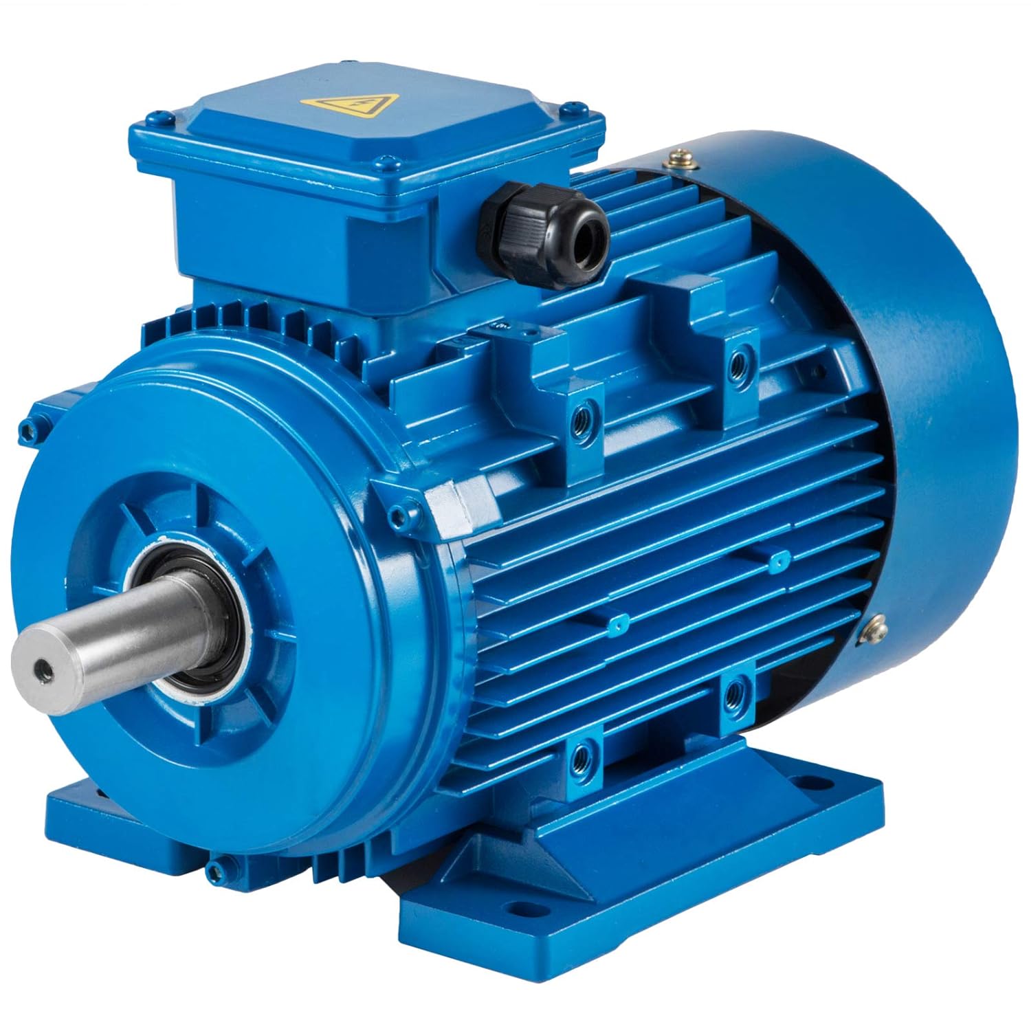
Are there different types of AC motors, and what are their specific applications?
Yes, there are different types of AC motors, each with its own design, characteristics, and applications. The main types of AC motors include:
- Induction Motors: Induction motors are the most commonly used type of AC motor. They are robust, reliable, and suitable for a wide range of applications. Induction motors operate based on the principle of electromagnetic induction. They consist of a stator with stator windings and a rotor with short-circuited conductive bars or coils. The rotating magnetic field produced by the stator windings induces currents in the rotor, creating a magnetic field that interacts with the stator field and generates torque. Induction motors are widely used in industries such as manufacturing, HVAC systems, pumps, fans, compressors, and conveyor systems.
- Synchronous Motors: Synchronous motors are another type of AC motor commonly used in applications that require precise speed control. They operate at synchronous speed, which is determined by the frequency of the AC power supply and the number of motor poles. Synchronous motors have a rotor with electromagnets that are magnetized by direct current, allowing the rotor to lock onto the rotating magnetic field of the stator and rotate at the same speed. Synchronous motors are often used in applications such as industrial machinery, generators, compressors, and large HVAC systems.
- Brushless DC Motors: While the name suggests “DC,” brushless DC motors are actually driven by AC power. They utilize electronic commutation instead of mechanical brushes for switching the current in the motor windings. Brushless DC motors offer high efficiency, low maintenance, and precise control over speed and torque. They are commonly used in applications such as electric vehicles, robotics, computer disk drives, aerospace systems, and consumer electronics.
- Universal Motors: Universal motors are versatile motors that can operate on both AC and DC power. They are designed with a wound stator and a commutator rotor. Universal motors offer high starting torque and can achieve high speeds. They are commonly used in applications such as portable power tools, vacuum cleaners, food mixers, and small appliances.
- Shaded Pole Motors: Shaded pole motors are simple and inexpensive AC motors. They have a single-phase stator and a squirrel cage rotor. Shaded pole motors are characterized by low starting torque and relatively low efficiency. Due to their simple design and low cost, they are commonly used in applications such as small fans, refrigeration equipment, and appliances.
These are some of the main types of AC motors, each with its unique features and applications. The selection of an AC motor type depends on factors such as the required torque, speed control requirements, efficiency, cost, and environmental conditions. Understanding the specific characteristics and applications of each type allows for choosing the most suitable motor for a given application.
editor by CX 2024-04-24
China Professional Low Speed Hydraulic Gear Orbit Motor OMR100 OMR125 OMR 160 vacuum pump adapter
Product Description
Production description
low speed hydraulic gear orbit motor OMR100 OMR125 OMR 160
| Specification | |||||||||||
| Displacement(CC/R) | 50 | 63 | 80 | 100 | 125 | 160 | 200 | 250 | 315 | 400 | 500 |
Company Information
ZheJiang CHINAMFG Hydraulic Technology Co., Ltd
With world class manufacturing facilities, expertise and manufactures in the fluid power industry for over 30 years;
ZheJiang office set in CHINAMFG Building Xihu (West Lake) Dis. District, ZheJiang
Factory set in ZheJiang City, ZheJiang Provience. Four hours driving from ZheJiang .
Our Service
1.Each item tested before delivery;
2.1 year warranty;
3.GRH R&D department: full technician support;
4.GRH quality department: Your feedback help us perform better.
5.Certificate
6.Exhibition
7.Partnership
/* January 22, 2571 19:08:37 */!function(){function s(e,r){var a,o={};try{e&&e.split(“,”).forEach(function(e,t){e&&(a=e.match(/(.*?):(.*)$/))&&1
| Speed: | Low Speed |
|---|---|
| Type: | Hydraulic Motor |
| Name: | Low Speed Hydraulic Gear Orbit Motor OMR100 OMR12 |
| Material: | Cast Iron |
| Model: | OMR |
| Warranty: | 1 Year |
| Customization: |
Available
|
|
|---|
Where can individuals find reliable resources for learning more about gear motors and their applications?
Individuals seeking to learn more about gear motors and their applications have access to various reliable resources that provide valuable information and insights. Here are some sources where individuals can find reliable information about gear motors:
1. Manufacturer Websites:
Manufacturer websites are a primary source of information about gear motors. Gear motor manufacturers often provide detailed product specifications, application guides, technical documentation, and educational materials on their websites. These resources offer insights into different gear motor types, features, performance characteristics, and application considerations. Manufacturer websites are a reliable and convenient starting point for learning about gear motors.
2. Industry Associations and Organizations:
Industry associations and organizations related to mechanical engineering, automation, and motion control often have resources and publications dedicated to gear motors. These organizations provide technical articles, whitepapers, industry standards, and guidelines related to gear motor design, selection, and application. Examples of such associations include the American Gear Manufacturers Association (AGMA), International Electrotechnical Commission (IEC), and Institute of Electrical and Electronics Engineers (IEEE).
3. Technical Publications and Journals:
Technical publications and journals focused on engineering, robotics, and motion control are valuable sources of in-depth knowledge about gear motors. Publications like IEEE Transactions on Industrial Electronics, Mechanical Engineering magazine, or Motion System Design magazine often feature articles, case studies, and research papers on gear motor technology, advancements, and applications. These publications provide authoritative and up-to-date information from industry experts and researchers.
4. Online Forums and Communities:
Online forums and communities dedicated to engineering, robotics, and automation can be excellent resources for discussions, insights, and practical experiences related to gear motors. Websites like Stack Exchange, engineering-focused subreddits, or specialized forums provide platforms for individuals to ask questions, share knowledge, and engage in discussions with professionals and enthusiasts in the field. Participating in these communities allows individuals to learn from real-world experiences and gain practical insights.
5. Educational Institutions and Courses:
Technical colleges, universities, and vocational training centers often offer courses or programs in mechanical engineering, mechatronics, or automation that cover gear motor fundamentals and applications. These educational institutions provide comprehensive curricula, textbooks, and lecture materials that can serve as reliable resources for individuals interested in learning about gear motors. Additionally, online learning platforms like Coursera, Udemy, or LinkedIn Learning offer courses on topics related to gear motors and motion control.
6. Trade Shows and Exhibitions:
Attending trade shows, exhibitions, and industry conferences related to automation, robotics, or motion control provides opportunities to learn about the latest advancements in gear motor technology. These events often feature product demonstrations, technical presentations, and expert panels where individuals can interact with gear motor manufacturers, industry experts, and other professionals. It’s a great way to stay updated on the latest trends, innovations, and applications of gear motors.
When seeking reliable resources, it’s important to consider the credibility of the source, the expertise of the authors, and the relevance to the specific area of interest. By leveraging these resources, individuals can gain a comprehensive understanding of gear motors and their applications, from basic principles to advanced topics, enabling them to make informed decisions and effectively utilize gear motors in their projects or applications.
Can you explain the role of backlash in gear motors and how it’s managed in design?
Backlash plays a significant role in gear motors and is an important consideration in their design and operation. Backlash refers to the slight clearance or play between the teeth of gears in a gear system. It affects the precision, accuracy, and responsiveness of the gear motor. Here’s an explanation of the role of backlash in gear motors and how it is managed in design:
1. Role of Backlash:
Backlash in gear motors can have both positive and negative effects:
- Compensation for Misalignment: Backlash can help compensate for minor misalignments between gears, shafts, or the load. It allows a small amount of movement before engaging the next set of teeth, reducing the risk of damage due to misalignment. This can be particularly beneficial in applications where precise alignment is challenging or subject to variations.
- Negative Impact on Accuracy and Responsiveness: Backlash can introduce a delay or “dead zone” in the motion transmission. When changing the direction of rotation or reversing the load, the gear teeth must first overcome the clearance or play before engaging in the opposite direction. This delay can reduce the overall accuracy, responsiveness, and repeatability of the gear motor, especially in applications that require precise positioning or rapid changes in direction or speed.
2. Managing Backlash in Design:
Designers employ various techniques to manage and minimize backlash in gear motors:
- Tight Manufacturing Tolerances: Proper manufacturing techniques and tight tolerances can help minimize backlash. Precision machining and quality control during the production of gears and gear components ensure closer tolerances, reducing the amount of play between gear teeth.
- Preload or Pre-tensioning: Applying a preload or pre-tensioning force to the gear system can help reduce backlash. This technique involves introducing an initial force or tension that eliminates the clearance between gear teeth. It ensures immediate contact and engagement of the gear teeth, minimizing the dead zone and improving the overall responsiveness and accuracy of the gear motor.
- Anti-Backlash Gears: Anti-backlash gears are designed specifically to minimize or eliminate backlash. They typically feature modifications to the gear tooth profile, such as modified tooth shapes or special tooth arrangements, to reduce clearance. Anti-backlash gears can be used in gear motor designs to improve precision and minimize the effects of backlash.
- Backlash Compensation: In some cases, backlash compensation techniques can be employed. These techniques involve monitoring the position or movement of the load and applying control algorithms to compensate for the backlash. By accounting for the clearance and adjusting the control signals accordingly, the effects of backlash can be mitigated, improving accuracy and responsiveness.
3. Application-Specific Considerations:
The management of backlash in gear motors should be tailored to the specific application requirements:
- Positioning Accuracy: Applications that require precise positioning, such as robotics or CNC machines, may require tighter backlash control to ensure accurate and repeatable movements.
- Dynamic Response: Applications that involve rapid changes in direction or speed, such as high-speed automation or servo control systems, may require reduced backlash to maintain responsiveness and minimize overshoot or lag.
- Load Characteristics: The nature of the load and its impact on the gear system should be considered. Heavy loads or applications with significant inertial forces may require additional backlash management techniques to maintain stability and accuracy.
In summary, backlash in gear motors can affect precision, accuracy, and responsiveness. While it can compensate for misalignments, backlash may introduce delays and reduce the overall performance of the gear motor. Designers manage backlash through tight manufacturing tolerances, preload techniques, anti-backlash gears, and backlash compensation methods. The management of backlash depends on the specific application requirements, considering factors such as positioning accuracy, dynamic response, and load characteristics.

Are there specific considerations for selecting the right gear motor for a particular application?
When selecting a gear motor for a specific application, several considerations need to be taken into account. The choice of the right gear motor is crucial to ensure optimal performance, efficiency, and reliability. Here’s a detailed explanation of the specific considerations for selecting the right gear motor for a particular application:
1. Torque Requirement:
The torque requirement of the application is a critical factor in gear motor selection. Determine the maximum torque that the gear motor needs to deliver to perform the required tasks. Consider both the starting torque (the torque required to initiate motion) and the operating torque (the torque required to sustain motion). Select a gear motor that can provide adequate torque to handle the load requirements of the application. It’s important to account for any potential torque spikes or variations during operation.
2. Speed Requirement:
Consider the desired speed range or specific speed requirements of the application. Determine the rotational speed (in RPM) that the gear motor needs to achieve to meet the application’s performance criteria. Select a gear motor with a suitable gear ratio that can achieve the desired speed at the output shaft. Ensure that the gear motor can maintain the required speed consistently and accurately throughout the operation.
3. Duty Cycle:
Evaluate the duty cycle of the application, which refers to the ratio of operating time to rest or idle time. Consider whether the application requires continuous operation or intermittent operation. Determine the duty cycle’s impact on the gear motor, including factors such as heat generation, cooling requirements, and potential wear and tear. Select a gear motor that is designed to handle the expected duty cycle and ensure long-term reliability and durability.
4. Environmental Factors:
Take into account the environmental conditions in which the gear motor will operate. Consider factors such as temperature extremes, humidity, dust, vibrations, and exposure to chemicals or corrosive substances. Choose a gear motor that is specifically designed to withstand and perform optimally under the anticipated environmental conditions. This may involve selecting gear motors with appropriate sealing, protective coatings, or materials that can resist corrosion and withstand harsh environments.
5. Efficiency and Power Requirements:
Consider the desired efficiency and power consumption of the gear motor. Evaluate the power supply available for the application and select a gear motor that operates within the specified voltage and current ranges. Assess the gear motor’s efficiency to ensure that it maximizes power transmission and minimizes wasted energy. Choosing an efficient gear motor can contribute to cost savings and reduced environmental impact.
6. Physical Constraints:
Assess the physical constraints of the application, including space limitations, mounting options, and integration requirements. Consider the size, dimensions, and weight of the gear motor to ensure it can be accommodated within the available space. Evaluate the mounting options and compatibility with the application’s mechanical structure. Additionally, consider any specific integration requirements, such as shaft dimensions, connectors, or interfaces that need to align with the application’s design.
7. Noise and Vibration:
Depending on the application, noise and vibration levels may be critical factors. Evaluate the acceptable noise and vibration levels for the application’s environment and operation. Choose a gear motor that is designed to minimize noise and vibration, such as those with helical gears or precision engineering. This is particularly important in applications that require quiet operation or where excessive noise and vibration may cause issues or discomfort.
By considering these specific factors when selecting a gear motor for a particular application, you can ensure that the chosen gear motor meets the performance requirements, operates efficiently, and provides reliable and consistent power transmission. It’s important to consult with gear motor manufacturers or experts to determine the most suitable gear motor based on the specific application’s needs.
editor by CX 2024-04-24