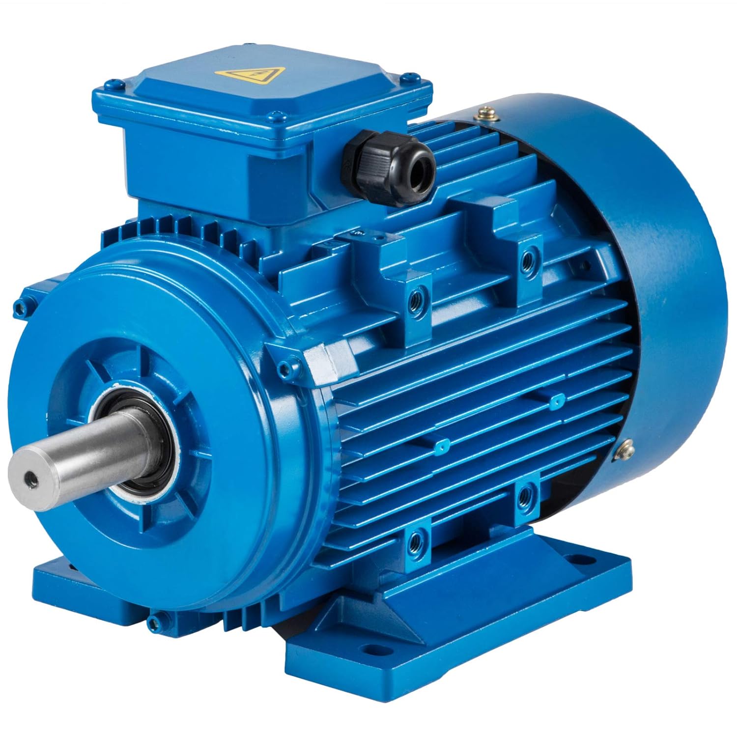
Product Description
3 Phase Ac Induction Motor is made of high quality cast iron.With optimized construction design,they can ensure the requirement of structure rigidity and intensity.Silicon steel plate is used in stator core and rotor core,it has good insulation on surface,low loss which ensures the higher efficiency.High quality insulation material combines the perfect insulation system which makes the insulation completely without clearance,high rigidity of the winding end,it can endure switching and reversing intensity,F class insulation makes the motor with higher heat stability and longer life.
Application:
Supply power:voltage variable ±5%,frequency variable:±2%,combine voltage and frequency variable:±5%.
The following as options or customers’ request:
-Protection class IP56
-Space heater
-Heat protector
-Vibration detector
-Special mounting dimension and shaft dimension
-Low vibration and low noise
-Bearing thermometer PT100(frame size H180 and above)
-Winding thermometer PT100
-Special painting
-Others
Manufacturing process:
- Stamping of lamination
- Rotor die-casting
- Winding and inserting – both manual and semi-automatically
- Vacuum varnishing
- Machining shaft, housing, end shields, etc…
- Rotor balancing
- Painting – both wet paint and powder coating
- Motor assembly
- Packing
- Inspecting spare parts every processing
- 100% test after each process and final test before packing
/* January 22, 2571 19:08:37 */!function(){function s(e,r){var a,o={};try{e&&e.split(“,”).forEach(function(e,t){e&&(a=e.match(/(.*?):(.*)$/))&&1
| Application: | Universal |
|---|---|
| Operating Speed: | Low Speed |
| Number of Stator: | Three-Phase |
| Species: | Explosion-Proof Three-Phase |
| Rotor Structure: | Winding Type |
| Casing Protection: | Closed Type |
| Customization: |
Available
|
|
|---|

What role do AC motors play in HVAC (heating, ventilation, and air conditioning) systems?
In HVAC (heating, ventilation, and air conditioning) systems, AC motors play a crucial role in various components and functions. These motors are responsible for powering fans, compressors, pumps, and other essential equipment within the HVAC system. Let’s explore the specific roles of AC motors in HVAC systems:
- Air Handling Units (AHUs) and Ventilation Systems: AC motors drive the fans in AHUs and ventilation systems. These fans draw in fresh air, circulate air within the building, and exhaust stale air. The motors provide the necessary power to move air through the ductwork and distribute it evenly throughout the space. They play a key role in maintaining proper indoor air quality, controlling humidity, and ensuring adequate ventilation.
- Chillers and Cooling Towers: HVAC systems that use chillers for cooling rely on AC motors to drive the compressor. The motor powers the compressor, which circulates refrigerant through the system, absorbing heat from the indoor environment and releasing it outside. AC motors are also used in cooling towers, which dissipate heat from the chiller system by evaporating water. The motors drive the fans that draw air through the cooling tower and enhance heat transfer.
- Heat Pumps: AC motors are integral components of heat pump systems, which provide both heating and cooling. The motor drives the compressor in the heat pump, enabling the transfer of heat between the indoor and outdoor environments. During cooling mode, the motor circulates refrigerant to extract heat from indoors and release it outside. In heating mode, the motor reverses the refrigerant flow to extract heat from the outdoor air or ground and transfer it indoors.
- Furnaces and Boilers: In heating systems, AC motors power the blowers or fans in furnaces and boilers. The motor drives the blower to distribute heated air or steam throughout the building. This helps maintain a comfortable indoor temperature and ensures efficient heat distribution in the space.
- Pumps and Circulation Systems: HVAC systems often incorporate pumps for water circulation, such as in hydronic heating or chilled water systems. AC motors drive these pumps, providing the necessary pressure to circulate water or other heat transfer fluids through the system. The motors ensure efficient flow rates and contribute to the effective transfer of thermal energy.
- Dampers and Actuators: AC motors are used in HVAC systems to control airflow and regulate the position of dampers and actuators. These motors enable the adjustment of airflow rates, temperature control, and zone-specific climate control. By modulating the motor speed or position, HVAC systems can achieve precise control of air distribution and temperature in different areas of a building.
AC motors in HVAC systems are designed to meet specific performance requirements, such as variable speed control, energy efficiency, and reliable operation under varying loads. Maintenance and regular inspection of these motors are essential to ensure optimal performance, energy efficiency, and longevity of the HVAC system.
In conclusion, AC motors play vital roles in HVAC systems by powering fans, compressors, pumps, and actuators. They enable proper air circulation, temperature control, and efficient transfer of heat, contributing to the overall comfort, air quality, and energy efficiency of buildings.
What are the safety considerations when working with or around AC motors?
Working with or around AC motors requires careful attention to safety to prevent accidents, injuries, and electrical hazards. Here are some important safety considerations to keep in mind:
- Electrical Hazards: AC motors operate on high voltage electrical systems, which pose a significant electrical hazard. It is essential to follow proper lockout/tagout procedures when working on motors to ensure that they are de-energized and cannot accidentally start up. Only qualified personnel should perform electrical work on motors, and they should use appropriate personal protective equipment (PPE), such as insulated gloves, safety glasses, and arc flash protection, to protect themselves from electrical shocks and arc flash incidents.
- Mechanical Hazards: AC motors often drive mechanical equipment, such as pumps, fans, or conveyors, which can present mechanical hazards. When working on or near motors, it is crucial to be aware of rotating parts, belts, pulleys, or couplings that can cause entanglement or crushing injuries. Guards and safety barriers should be in place to prevent accidental contact with moving parts, and proper machine guarding principles should be followed. Lockout/tagout procedures should also be applied to the associated mechanical equipment to ensure it is safely de-energized during maintenance or repair.
- Fire and Thermal Hazards: AC motors can generate heat during operation, and in some cases, excessive heat can pose a fire hazard. It is important to ensure that motors are adequately ventilated to dissipate heat and prevent overheating. Motor enclosures and cooling systems should be inspected regularly to ensure proper functioning. Additionally, combustible materials should be kept away from motors to reduce the risk of fire. If a motor shows signs of overheating or emits a burning smell, it should be immediately shut down and inspected by a qualified professional.
- Proper Installation and Grounding: AC motors should be installed and grounded correctly to ensure electrical safety. Motors should be installed according to manufacturer guidelines, including proper alignment, mounting, and connection of electrical cables. Adequate grounding is essential to prevent electrical shocks and ensure the safe dissipation of fault currents. Grounding conductors, such as grounding rods or grounding straps, should be properly installed and regularly inspected to maintain their integrity.
- Safe Handling and Lifting: AC motors can be heavy and require proper handling and lifting techniques to prevent musculoskeletal injuries. When moving or lifting motors, equipment such as cranes, hoists, or forklifts should be used, and personnel should be trained in safe lifting practices. It is important to avoid overexertion and use proper lifting tools, such as slings or lifting straps, to distribute the weight evenly and prevent strain or injury.
- Training and Awareness: Proper training and awareness are critical for working safely with or around AC motors. Workers should receive training on electrical safety, lockout/tagout procedures, personal protective equipment usage, and safe work practices. They should be familiar with the specific hazards associated with AC motors and understand the appropriate safety precautions to take. Regular safety meetings and reminders can help reinforce safe practices and keep safety at the forefront of everyone’s minds.
It is important to note that the safety considerations mentioned above are general guidelines. Specific safety requirements may vary depending on the motor size, voltage, and the specific workplace regulations and standards in place. It is crucial to consult relevant safety codes, regulations, and industry best practices to ensure compliance and maintain a safe working environment when working with or around AC motors.
What is an AC motor, and how does it differ from a DC motor?
An AC motor, also known as an alternating current motor, is a type of electric motor that operates on alternating current. It converts electrical energy into mechanical energy through the interaction of magnetic fields. AC motors are widely used in various applications, ranging from household appliances to industrial machinery. Here’s a detailed explanation of what an AC motor is and how it differs from a DC motor:
AC Motor:
An AC motor consists of two main components: the stator and the rotor. The stator is the stationary part of the motor and contains the stator windings. These windings are typically made of copper wire and are arranged in specific configurations to create a rotating magnetic field when energized by an alternating current. The rotor, on the other hand, is the rotating part of the motor and is typically made of laminated steel cores with conducting bars or coils. The rotor windings are connected to a shaft, and their interaction with the rotating magnetic field produced by the stator causes the rotor to rotate.
The operation of an AC motor is based on the principles of electromagnetic induction. When the stator windings are energized with an AC power supply, the changing magnetic field induces a voltage in the rotor windings, which in turn creates a magnetic field. The interaction between the rotating magnetic field of the stator and the magnetic field of the rotor produces a torque, causing the rotor to rotate. The speed of rotation depends on the frequency of the AC power supply and the number of poles in the motor.
DC Motor:
A DC motor, also known as a direct current motor, operates on direct current. Unlike an AC motor, which relies on the interaction of magnetic fields to generate torque, a DC motor uses the principle of commutation to produce rotational motion. A DC motor consists of a stator and a rotor, similar to an AC motor. The stator contains the stator windings, while the rotor consists of a rotating armature with coils or permanent magnets.
In a DC motor, when a direct current is applied to the stator windings, a magnetic field is created. The rotor, either through the use of brushes and a commutator or electronic commutation, aligns itself with the magnetic field and begins to rotate. The direction of the current in the rotor windings is continuously reversed to ensure continuous rotation. The speed of a DC motor can be controlled by adjusting the voltage applied to the motor or by using electronic speed control methods.
Differences:
The main differences between AC motors and DC motors are as follows:
- Power Source: AC motors operate on alternating current, which is the standard power supply in most residential and commercial buildings. DC motors, on the other hand, require direct current and typically require a power supply that converts AC to DC.
- Construction: AC motors and DC motors have similar construction with stators and rotors, but the design and arrangement of the windings differ. AC motors generally have three-phase windings, while DC motors can have either armature windings or permanent magnets.
- Speed Control: AC motors typically operate at fixed speeds determined by the frequency of the power supply and the number of poles. DC motors, on the other hand, offer more flexibility in speed control and can be easily adjusted over a wide range of speeds.
- Efficiency: AC motors are generally more efficient than DC motors. AC motors can achieve higher power densities and are often more suitable for high-power applications. DC motors, however, offer better speed control and are commonly used in applications that require precise speed regulation.
- Applications: AC motors are widely used in applications such as industrial machinery, HVAC systems, pumps, and compressors. DC motors find applications in robotics, electric vehicles, computer disk drives, and small appliances.
In conclusion, AC motors and DC motors differ in their power source, construction, speed control, efficiency, and applications. AC motors rely on the interaction of magnetic fields and operate on alternating current, while DC motors use commutation and operate on direct current. Each type of motor has its advantages and is suited for different applications based on factors such as power requirements, speed control needs, and efficiency considerations.


editor by CX 2024-05-07
China supplier Air Conditioner Cbb65 AC Motor Run Capacitor Water Cooled Capacitor vacuum pump and compressor
Product Description
Recommend view more >>
|
Model Number: |
CBB65 air conditioner capacitor |
|
|
Type |
Polypropylene film capacitor |
|
|
Safety approvals: |
CQC/VDE/TUV/CL |
|
|
Approval standard |
GB/T3667,EN65712 |
|
|
Climatic category |
25/70/21,25/85/21,40/70/21,40/85/21 |
|
|
Rated voltage |
150VAC~600VAC(50-60Hz) |
|
|
Capacitance range |
3uf~100uf |
|
|
Capacitance tolerance |
+_5%(J),+_10%(K),+10%(U),-5%(U) |
|
|
Testing voltage |
|
|
|
Between terminals |
2*Un(VAC)/5s |
|
|
Between terminals and case |
2*Un+1000(VAC)/5s(>=2000VAC) |
|
|
Insulation Resistance(20) |
|
|
|
Between terminals |
>=2000MΩ,UF(500VDC,5s) |
|
|
Tangent of loss angle(20) |
<=0.002(100Hz) |
|
|
Class of safety protection |
S0/S3 |
|
|
Fault Currency |
10,000AFC(UL810) |
|
|
Place of CHINAMFG |
CHINA |
|
|
Packing |
More pieces in 1 inner box or polybag as customer request. |
|
|
Color |
accept customization |
|
|
Supplier type |
OEM factory |
|
|
Capacitance(uf) |
250/300VAC |
|
|
400-450VAC |
|
|
||||
|
|
Cylindrical |
|
Ocal |
Cylindrical |
|
Ocal |
||||
|
|
D |
H |
L*W*H |
H |
D |
L*W*H |
||||
|
10uf |
40 |
55 |
51.5*31.5*65 |
30 |
60 |
51.5*31.5*65 |
||||
|
15uf |
40 |
55 |
51.5*31.5*65 |
35 |
60 |
/ |
||||
|
20uf |
40 |
65 |
51.5*31.5*65 |
40 |
60 |
51.5*31.5*75 |
||||
|
25uf |
40 |
65 |
51.5*31.5*65 |
40 |
60 |
51.5*31.5*85 |
||||
|
30uf |
/ |
/ |
/ |
40 |
70 |
71.5*45*75 |
||||
|
35uf |
40 |
75 |
71.5*45*75 |
45 |
70 |
/ |
||||
|
40uf |
/ |
/ |
/ |
45 |
70 |
71.5*45*85 |
||||
|
45uf |
45 |
75 |
71.5*45*75 |
45 |
80 |
/ |
||||
|
50uf |
45 |
85 |
71.5*45*85 |
45 |
90 |
71.5*45*100 |
||||
|
60uf |
45 |
95 |
71.5*45*100 |
50 |
90 |
/ |
||||
What’s a dual run AC capacitor ?
* A capacitor is an electric component that temporarily stores an electrical charge and AC capacitor is a key component to start
air conditioner motors.
* A dual run capacitor supports “TWO” electric motors, 1 section for the condenser fan motor and the other for the compressor
motor. Beacause of technological innovation, the dual run capacitor can saves space by combining 2 capacitors into 1 case.
* Round cylinder-shaped dual run capacitors are commonly used for air conditioning, it can help in the starting of the compressor
and the condenser fan motor.
* Air conditioner capacitor is small in size, lightweight, heat resisting and anti-explosion.
Dual capacitors come in a variety of sizes, depending on the capacitance (µF or MFD) and the voltage.
1. The capacitance (µF or MFD) must be the same or stay within ±6% of its original value. Example: 45 µF cap can be substituted
by 42.3 to 47.7 µF with the same or better voltage ratings capacitor .
2. A 440 volt capacitor can be used in place of a 370 volt capacitor, as it can work better, but the 370 volt capacitor can’t be
used in place of a 440 volt capacitor.It will work for a while or will fail prematurely, because exceeding the capacitor’s
rated voltage will cause the dielectric to break down and the capacitor to short out.
“TIME” to Replace
The Dual Run AC Capacitor needs to be replaced when the following conditions occur:
1. The fan wouldn’t spin – the condenser fan motor maybe died.
2. The air conditioner is making humming sound, but no air flow.
3. Air conditioner stopped cooling – the compressor in the condenser maybe not coming on.
“SUPER EASY” to Install
* First, Shut off power to the A/C at both the thermostat and the breaker box. Secondly, taking out the capacitor.
* What’s important, make sure you know which wire is for which terminal – 3 terminals on the top are labeled “Herm”/”H” for
the compressor motor, “Fan”/”F” for the fan and “C” for the common line.
* Direct replacement, no need to change wiring or adapter.
* Last but not least, self-install will save you a substantial amount of money!
What is a starting capacitor and a running capacitor for a motor?
As we all know, a single-phase AC motor is not like a three-phase motor. It can turn when it is powered. It needs a starting torque to rotate, and the clockwise and anti-clockwise of this torque determines the steering of the motor, and there are many
ways to start. Among them, the capacitor start is one, which is customarily called the start capacitor, and the single-phase motor needs it to rotate smoothly.
However, some single-phase motors have more than 1 capacitor, and some motors have 2 capacitors. Why? Because some motors are equipped with a starting capacitor and a running capacitor, what is going on?
The difference between start capacitors and run capacitors.
Running capacitor: It is connected to the secondary winding to form an alternating magnetic field after phase-shifting the alternating current, and forms an approximately circular elliptical rotating magnetic field with the alternating magnetic field of the main winding. So he can be the same capacitor, but its role is different.
No matter what kind of capacitor, it has a starting effect at the beginning of the motor. However, when the motor reaches about 75% of the rated speed, the starting capacitor is automatically disconnected by the centrifugal switch, and the running capacitor continues to work with the motor. The process of starting the motor is actually the process of “column phase”. Because a single-phase motor is different from a three-phase motor, there is no phase difference, and a rotating magnetic field cannot be generated. The function of the capacitor is to make the starting winding current of the motor lead the running winding by 90 electrical angles in time and space to form a phase difference. Among them, the running capacitor also plays the role of balancing the current between the main and auxiliary windings. Since the starting capacitor works for an instant and a short time, the withstand voltage is required to be above 250V, while the running capacitor needs to work for a long time, and the withstand voltage is required to be above 450V.
The starting capacitor is to make the starting coil of the single-phase motor energized at the time of starting, and then cut off after starting. The running capacitor is to make the motor perform capacitance compensation during the operation, so the starting capacitor cannot be less, and the running capacitor can not be used.
The running capacitor is the starting capacitor used when the press is working normally. When the press starts, it starts the press together with the running capacitor. After the press is turned up, the start capacitor is disconnected. The running and starting capacitors are together, but 1 of the starting capacitors is open, and the starting capacitor is useless when the motor turns. What is the difference between the starting capacitor and the running capacitor? That is the capacity of the starting capacitor is large, generally 2-5 times that of the running capacitor, while the capacity of the running capacitor is small, and the capacity difference between the 2 is huge and easy to distinguish.
/* January 22, 2571 19:08:37 */!function(){function s(e,r){var a,o={};try{e&&e.split(“,”).forEach(function(e,t){e&&(a=e.match(/(.*?):(.*)$/))&&1
| Application: | Industrial |
|---|---|
| Certification: | ISO9001, CE |
| Specification: | CH86 |
| Customization: |
Available
|
|
|---|
.shipping-cost-tm .tm-status-off{background: none;padding:0;color: #1470cc}
|
Shipping Cost:
Estimated freight per unit. |
about shipping cost and estimated delivery time. |
|---|
| Payment Method: |
|
|---|---|
|
Initial Payment Full Payment |
| Currency: | US$ |
|---|
| Return&refunds: | You can apply for a refund up to 30 days after receipt of the products. |
|---|

Are there environmental considerations associated with the use of AC motors?
Yes, there are several environmental considerations associated with the use of AC motors. These considerations are primarily related to energy consumption, greenhouse gas emissions, and the disposal of motors at the end of their life cycle. Let’s explore these environmental considerations in detail:
- Energy Efficiency: AC motors can have varying levels of energy efficiency, which directly impacts their environmental impact. Motors with higher efficiency convert a larger percentage of electrical energy into useful mechanical work, resulting in reduced energy consumption. By selecting and using high-efficiency AC motors, energy usage can be minimized, leading to lower greenhouse gas emissions and reduced reliance on fossil fuels for electricity generation.
- Greenhouse Gas Emissions: The electricity consumed by AC motors is often produced by power plants that burn fossil fuels, such as coal, natural gas, or oil. The generation of electricity from these fossil fuels releases greenhouse gases, contributing to climate change. By employing energy-efficient motors and optimizing motor systems, businesses and individuals can reduce their electricity demand, leading to lower greenhouse gas emissions and a smaller carbon footprint.
- Motor Disposal and Recycling: AC motors contain various materials, including metals, plastics, and electrical components. At the end of their life cycle, proper disposal or recycling is important to minimize their environmental impact. Some components, such as copper windings and steel casings, can be recycled, reducing the need for new raw materials and energy-intensive manufacturing processes. It is crucial to follow local regulations and guidelines for the disposal and recycling of motors to prevent environmental pollution and promote resource conservation.
- Manufacturing and Production: The manufacturing and production processes associated with AC motors can have environmental implications. The extraction and processing of raw materials, such as metals and plastics, can result in habitat destruction, energy consumption, and greenhouse gas emissions. Additionally, the manufacturing processes themselves can generate waste and pollutants. Motor manufacturers can mitigate these environmental impacts by adopting sustainable practices, using recycled materials, reducing waste generation, and implementing energy-efficient production methods.
- Life Cycle Assessment: Conducting a life cycle assessment (LCA) of AC motors can provide a holistic view of their environmental impact. An LCA considers the environmental aspects associated with the entire life cycle of the motor, including raw material extraction, manufacturing, transportation, use, and end-of-life disposal or recycling. By analyzing the different stages of the motor’s life cycle, stakeholders can identify opportunities for improvement, such as optimizing energy efficiency, reducing emissions, and implementing sustainable practices.
To address these environmental considerations, governments, organizations, and industry standards bodies have developed regulations and guidelines to promote energy efficiency and reduce the environmental impact of AC motors. These include efficiency standards, labeling programs, and incentives for the use of high-efficiency motors. Additionally, initiatives promoting motor system optimization, such as proper motor sizing, maintenance, and control, can further enhance energy efficiency and minimize environmental impact.
In summary, the environmental considerations associated with the use of AC motors include energy efficiency, greenhouse gas emissions, motor disposal and recycling, manufacturing processes, and life cycle assessment. By prioritizing energy efficiency, proper disposal, recycling, and sustainable manufacturing practices, the environmental impact of AC motors can be minimized, contributing to a more sustainable and environmentally conscious approach to motor usage.
What are the safety considerations when working with or around AC motors?
Working with or around AC motors requires careful attention to safety to prevent accidents, injuries, and electrical hazards. Here are some important safety considerations to keep in mind:
- Electrical Hazards: AC motors operate on high voltage electrical systems, which pose a significant electrical hazard. It is essential to follow proper lockout/tagout procedures when working on motors to ensure that they are de-energized and cannot accidentally start up. Only qualified personnel should perform electrical work on motors, and they should use appropriate personal protective equipment (PPE), such as insulated gloves, safety glasses, and arc flash protection, to protect themselves from electrical shocks and arc flash incidents.
- Mechanical Hazards: AC motors often drive mechanical equipment, such as pumps, fans, or conveyors, which can present mechanical hazards. When working on or near motors, it is crucial to be aware of rotating parts, belts, pulleys, or couplings that can cause entanglement or crushing injuries. Guards and safety barriers should be in place to prevent accidental contact with moving parts, and proper machine guarding principles should be followed. Lockout/tagout procedures should also be applied to the associated mechanical equipment to ensure it is safely de-energized during maintenance or repair.
- Fire and Thermal Hazards: AC motors can generate heat during operation, and in some cases, excessive heat can pose a fire hazard. It is important to ensure that motors are adequately ventilated to dissipate heat and prevent overheating. Motor enclosures and cooling systems should be inspected regularly to ensure proper functioning. Additionally, combustible materials should be kept away from motors to reduce the risk of fire. If a motor shows signs of overheating or emits a burning smell, it should be immediately shut down and inspected by a qualified professional.
- Proper Installation and Grounding: AC motors should be installed and grounded correctly to ensure electrical safety. Motors should be installed according to manufacturer guidelines, including proper alignment, mounting, and connection of electrical cables. Adequate grounding is essential to prevent electrical shocks and ensure the safe dissipation of fault currents. Grounding conductors, such as grounding rods or grounding straps, should be properly installed and regularly inspected to maintain their integrity.
- Safe Handling and Lifting: AC motors can be heavy and require proper handling and lifting techniques to prevent musculoskeletal injuries. When moving or lifting motors, equipment such as cranes, hoists, or forklifts should be used, and personnel should be trained in safe lifting practices. It is important to avoid overexertion and use proper lifting tools, such as slings or lifting straps, to distribute the weight evenly and prevent strain or injury.
- Training and Awareness: Proper training and awareness are critical for working safely with or around AC motors. Workers should receive training on electrical safety, lockout/tagout procedures, personal protective equipment usage, and safe work practices. They should be familiar with the specific hazards associated with AC motors and understand the appropriate safety precautions to take. Regular safety meetings and reminders can help reinforce safe practices and keep safety at the forefront of everyone’s minds.
It is important to note that the safety considerations mentioned above are general guidelines. Specific safety requirements may vary depending on the motor size, voltage, and the specific workplace regulations and standards in place. It is crucial to consult relevant safety codes, regulations, and industry best practices to ensure compliance and maintain a safe working environment when working with or around AC motors.
Are there different types of AC motors, and what are their specific applications?
Yes, there are different types of AC motors, each with its own design, characteristics, and applications. The main types of AC motors include:
- Induction Motors: Induction motors are the most commonly used type of AC motor. They are robust, reliable, and suitable for a wide range of applications. Induction motors operate based on the principle of electromagnetic induction. They consist of a stator with stator windings and a rotor with short-circuited conductive bars or coils. The rotating magnetic field produced by the stator windings induces currents in the rotor, creating a magnetic field that interacts with the stator field and generates torque. Induction motors are widely used in industries such as manufacturing, HVAC systems, pumps, fans, compressors, and conveyor systems.
- Synchronous Motors: Synchronous motors are another type of AC motor commonly used in applications that require precise speed control. They operate at synchronous speed, which is determined by the frequency of the AC power supply and the number of motor poles. Synchronous motors have a rotor with electromagnets that are magnetized by direct current, allowing the rotor to lock onto the rotating magnetic field of the stator and rotate at the same speed. Synchronous motors are often used in applications such as industrial machinery, generators, compressors, and large HVAC systems.
- Brushless DC Motors: While the name suggests “DC,” brushless DC motors are actually driven by AC power. They utilize electronic commutation instead of mechanical brushes for switching the current in the motor windings. Brushless DC motors offer high efficiency, low maintenance, and precise control over speed and torque. They are commonly used in applications such as electric vehicles, robotics, computer disk drives, aerospace systems, and consumer electronics.
- Universal Motors: Universal motors are versatile motors that can operate on both AC and DC power. They are designed with a wound stator and a commutator rotor. Universal motors offer high starting torque and can achieve high speeds. They are commonly used in applications such as portable power tools, vacuum cleaners, food mixers, and small appliances.
- Shaded Pole Motors: Shaded pole motors are simple and inexpensive AC motors. They have a single-phase stator and a squirrel cage rotor. Shaded pole motors are characterized by low starting torque and relatively low efficiency. Due to their simple design and low cost, they are commonly used in applications such as small fans, refrigeration equipment, and appliances.
These are some of the main types of AC motors, each with its unique features and applications. The selection of an AC motor type depends on factors such as the required torque, speed control requirements, efficiency, cost, and environmental conditions. Understanding the specific characteristics and applications of each type allows for choosing the most suitable motor for a given application.
editor by CX 2024-05-07
China high quality ZD Direct On-line Starting AC Right Angle Spiral Bevel Gear Motor For Packing Machine vacuum pump diy
Product Description
Model Selection
ZD Leader has a wide range of micro motor production lines in the industry, including DC Motor, AC Motor, Brushless Motor, Planetary Gear Motor, Drum Motor, Planetary Gearbox, RV Reducer and Harmonic Gearbox etc. Through technical innovation and customization, we help you create outstanding application systems and provide flexible solutions for various industrial automation situations.
• Model Selection
Our professional sales representive and technical team will choose the right model and transmission solutions for your usage depend on your specific parameters.
• Drawing Request
If you need more product parameters, catalogues, CAD or 3D drawings, please contact us.
• On Your Need
We can modify standard products or customize them to meet your specific needs.
Detailed Photos
Product Description
Features:
1) Dimensions: 80mm
2) Power:25W
3) Voltage(v): 220V
4) Speed(nS): 1550rpm
5) Reduction ratio: 1:100
Product Parameters
Other Related Products
Click here to find what you are looking for:
Company Profile
FAQ
Q: What’re your main products?
A: We currently produce Brushed Dc Motors, Brushed Dc Gear Motors, Planetary Dc Gear Motors, Brushless Dc Motors, Stepper motors, Ac Motors and High Precision Planetary Gear Box etc. You can check the specifications for above motors on our website and you can email us to recommend needed motors per your specification too.
Q: How to select a suitable motor?
A:If you have motor pictures or drawings to show us, or you have detailed specs like voltage, speed, torque, motor size, working mode of the motor, needed lifetime and noise level etc, please do not hesitate to let us know, then we can recommend suitable motor per your request accordingly.
Q: Do you have a customized service for your standard motors?
A: Yes, we can customize per your request for the voltage, speed, torque and shaft size/shape. If you need additional wires/cables soldered on the terminal or need to add connectors, or capacitors or EMC we can make it too.
Q: Do you have an individual design service for motors?
A: Yes, we would like to design motors individually for our customers, but it may need some mold developing cost and design charge.
Q: What’s your lead time?
A: Generally speaking, our regular standard product will need 15-30days, a bit longer for customized products. But we are very flexible on the lead time, it will depend on the specific orders.
/* January 22, 2571 19:08:37 */!function(){function s(e,r){var a,o={};try{e&&e.split(“,”).forEach(function(e,t){e&&(a=e.match(/(.*?):(.*)$/))&&1
| Application: | Industrial |
|---|---|
| Speed: | Constant Speed |
| Number of Stator: | Single-Phase |
| Function: | Driving |
| Casing Protection: | Closed Type |
| Number of Poles: | 2 |
| Customization: |
Available
|
|
|---|

Can gear motors be used in robotics, and if so, what are some notable applications?
Yes, gear motors are widely used in robotics due to their ability to provide torque, precise control, and compact size. They play a crucial role in various robotic applications, enabling the movement, manipulation, and control of robotic systems. Here are some notable applications of gear motors in robotics:
1. Robotic Arm Manipulation:
Gear motors are commonly used in robotic arms to provide precise and controlled movement. They enable the articulation of the arm’s joints, allowing the robot to reach different positions and orientations. Gear motors with high torque capabilities are essential for lifting, rotating, and manipulating objects with varying weights and sizes.
2. Mobile Robots:
Gear motors are employed in mobile robots, including wheeled robots and legged robots, to drive their locomotion. They provide the necessary torque and control for the robot to move, turn, and navigate in different environments. Gear motors with appropriate gear ratios ensure the robot’s mobility, stability, and maneuverability.
3. Robotic Grippers and End Effectors:
Gear motors are used in robotic grippers and end effectors to control the opening, closing, and gripping force. By integrating gear motors into the gripper mechanism, robots can grasp and manipulate objects of various shapes, sizes, and weights. The gear motors enable precise control over the gripping action, allowing the robot to handle delicate or fragile objects with care.
4. Autonomous Drones and UAVs:
Gear motors are utilized in the propulsion systems of autonomous drones and unmanned aerial vehicles (UAVs). They drive the propellers or rotors, providing the necessary thrust and control for the drone’s flight. Gear motors with high power-to-weight ratios, efficient energy conversion, and precise speed control are crucial for achieving stable and maneuverable flight in drones.
5. Humanoid Robots:
Gear motors are integral to the movement and functionality of humanoid robots. They are used in robotic joints, such as hips, knees, and shoulders, to enable human-like movements. Gear motors with appropriate torque and speed capabilities allow humanoid robots to walk, run, climb stairs, and perform complex motions resembling human actions.
6. Robotic Exoskeletons:
Gear motors play a vital role in robotic exoskeletons, which are wearable robotic devices designed to augment human strength and assist in physical tasks. Gear motors are used in the exoskeleton’s joints and actuators, providing the necessary torque and control to enhance human abilities. They enable users to perform tasks with reduced effort, assist in rehabilitation, or provide support in physically demanding environments.
These are just a few notable applications of gear motors in robotics. Their versatility, torque capabilities, precise control, and compact size make them indispensable components in various robotic systems. Gear motors enable robots to perform complex tasks, move with agility, interact with the environment, and assist humans in a wide range of applications, from industrial automation to healthcare and exploration.

What is the significance of gear reduction in gear motors, and how does it affect efficiency?
Gear reduction plays a significant role in gear motors as it enables the motor to deliver higher torque while reducing the output speed. This feature has several important implications for gear motors, including enhanced power transmission, improved control, and potential trade-offs in terms of efficiency. Here’s a detailed explanation of the significance of gear reduction in gear motors and its effect on efficiency:
Significance of Gear Reduction:
1. Increased Torque: Gear reduction allows gear motors to generate higher torque output compared to a motor without gears. By reducing the rotational speed at the output shaft, gear reduction increases the mechanical advantage of the system. This increased torque is beneficial in applications that require high torque to overcome resistance, such as lifting heavy loads or driving machinery with high inertia.
2. Improved Control: Gear reduction enhances the control and precision of gear motors. By reducing the speed, gear reduction allows for finer control over the motor’s rotational movement. This is particularly important in applications that require precise positioning or accurate speed control. The gear reduction mechanism enables gear motors to achieve smoother and more controlled movements, reducing the risk of overshooting or undershooting the desired position.
3. Load Matching: Gear reduction helps match the motor’s power characteristics to the load requirements. Different applications have varying torque and speed requirements. Gear reduction allows the gear motor to achieve a better match between the motor’s power output and the specific requirements of the load. It enables the motor to operate closer to its peak efficiency by optimizing the torque-speed trade-off.
Effect on Efficiency:
While gear reduction offers several advantages, it can also affect the efficiency of gear motors. Here’s how gear reduction impacts efficiency:
1. Mechanical Efficiency: The gear reduction process introduces mechanical components such as gears, bearings, and lubrication systems. These components introduce additional friction and mechanical losses into the system. As a result, some energy is lost in the form of heat during the gear reduction process. The efficiency of the gear motor is influenced by the quality of the gears, the lubrication used, and the overall design of the gear system. Well-designed and properly maintained gear systems can minimize these losses and optimize mechanical efficiency.
2. System Efficiency: Gear reduction affects the overall system efficiency by impacting the motor’s electrical efficiency. In gear motors, the motor typically operates at higher speeds and lower torques compared to a direct-drive motor. The overall system efficiency takes into account both the electrical efficiency of the motor and the mechanical efficiency of the gear system. While gear reduction can increase the torque output, it also introduces additional losses due to increased mechanical complexity. Therefore, the overall system efficiency may be lower compared to a direct-drive motor for certain applications.
It’s important to note that the efficiency of gear motors is influenced by various factors beyond gear reduction, such as motor design, control systems, and operating conditions. The selection of high-quality gears, proper lubrication, and regular maintenance can help minimize losses and improve efficiency. Additionally, advancements in gear technology, such as the use of precision gears and improved lubricants, can contribute to higher overall efficiency in gear motors.
In summary, gear reduction is significant in gear motors as it provides increased torque, improved control, and better load matching. However, gear reduction can introduce mechanical losses and affect the overall efficiency of the system. Proper design, maintenance, and consideration of application requirements are essential to optimize the balance between torque, speed, and efficiency in gear motors.

Are there specific considerations for selecting the right gear motor for a particular application?
When selecting a gear motor for a specific application, several considerations need to be taken into account. The choice of the right gear motor is crucial to ensure optimal performance, efficiency, and reliability. Here’s a detailed explanation of the specific considerations for selecting the right gear motor for a particular application:
1. Torque Requirement:
The torque requirement of the application is a critical factor in gear motor selection. Determine the maximum torque that the gear motor needs to deliver to perform the required tasks. Consider both the starting torque (the torque required to initiate motion) and the operating torque (the torque required to sustain motion). Select a gear motor that can provide adequate torque to handle the load requirements of the application. It’s important to account for any potential torque spikes or variations during operation.
2. Speed Requirement:
Consider the desired speed range or specific speed requirements of the application. Determine the rotational speed (in RPM) that the gear motor needs to achieve to meet the application’s performance criteria. Select a gear motor with a suitable gear ratio that can achieve the desired speed at the output shaft. Ensure that the gear motor can maintain the required speed consistently and accurately throughout the operation.
3. Duty Cycle:
Evaluate the duty cycle of the application, which refers to the ratio of operating time to rest or idle time. Consider whether the application requires continuous operation or intermittent operation. Determine the duty cycle’s impact on the gear motor, including factors such as heat generation, cooling requirements, and potential wear and tear. Select a gear motor that is designed to handle the expected duty cycle and ensure long-term reliability and durability.
4. Environmental Factors:
Take into account the environmental conditions in which the gear motor will operate. Consider factors such as temperature extremes, humidity, dust, vibrations, and exposure to chemicals or corrosive substances. Choose a gear motor that is specifically designed to withstand and perform optimally under the anticipated environmental conditions. This may involve selecting gear motors with appropriate sealing, protective coatings, or materials that can resist corrosion and withstand harsh environments.
5. Efficiency and Power Requirements:
Consider the desired efficiency and power consumption of the gear motor. Evaluate the power supply available for the application and select a gear motor that operates within the specified voltage and current ranges. Assess the gear motor’s efficiency to ensure that it maximizes power transmission and minimizes wasted energy. Choosing an efficient gear motor can contribute to cost savings and reduced environmental impact.
6. Physical Constraints:
Assess the physical constraints of the application, including space limitations, mounting options, and integration requirements. Consider the size, dimensions, and weight of the gear motor to ensure it can be accommodated within the available space. Evaluate the mounting options and compatibility with the application’s mechanical structure. Additionally, consider any specific integration requirements, such as shaft dimensions, connectors, or interfaces that need to align with the application’s design.
7. Noise and Vibration:
Depending on the application, noise and vibration levels may be critical factors. Evaluate the acceptable noise and vibration levels for the application’s environment and operation. Choose a gear motor that is designed to minimize noise and vibration, such as those with helical gears or precision engineering. This is particularly important in applications that require quiet operation or where excessive noise and vibration may cause issues or discomfort.
By considering these specific factors when selecting a gear motor for a particular application, you can ensure that the chosen gear motor meets the performance requirements, operates efficiently, and provides reliable and consistent power transmission. It’s important to consult with gear motor manufacturers or experts to determine the most suitable gear motor based on the specific application’s needs.
editor by CX 2024-05-07
China Good quality ZD CCC, CE, UL. RoHS Constant Speed Helical Gear AC Motor vacuum pump
Product Description
Model Selection
ZD Leader has a wide range of micro motor production lines in the industry, including DC Motor, AC Motor, Brushless Motor, Planetary Gear Motor, Drum Motor, Planetary Gearbox, RV Reducer and Harmonic Gearbox etc. Through technical innovation and customization, we help you create outstanding application systems and provide flexible solutions for various industrial automation situations.
• Model Selection
Our professional sales representive and technical team will choose the right model and transmission solutions for your usage depend on your specific parameters.
• Drawing Request
If you need more product parameters, catalogues, CAD or 3D drawings, please contact us.
• On Your Need
We can modify standard products or customize them to meet your specific needs.
Product Parameters
Helical Gear Motor
| Mount Type | Horizontal / Vertical |
| MOTOR TYPE | Induction Motor |
| OUTPUT POWER | 100W / 200W / 400W / 750W / 1500W / 2200W / 3700W (Can Be Customized) |
| OUTPUT SHAFT | 18mm / 22mm / 28mm / 32mm / 40mm / 50mm; Round Shaft, D-Cut Shaft, Key-Way Shaft (Can Be Customized) |
| Voltage type | Single phase 110V50/60Hz, 220V/50/60Hz; Three phase 220-240/380-415V, 50/60Hz |
| Accessories | Electric Brake / Fan / Terminal Box |
| Gear Ratio | 3K-1800K |
Type Of Helical Gear Motor
Other Products
Company Profile
/* January 22, 2571 19:08:37 */!function(){function s(e,r){var a,o={};try{e&&e.split(“,”).forEach(function(e,t){e&&(a=e.match(/(.*?):(.*)$/))&&1
| Application: | Moving Machinery |
|---|---|
| Operating Speed: | Constant Speed |
| Power Source: | AC Motor |
| Casing Protection: | Closed Type |
| Number of Poles: | 4 |
| Certification: | ISO9001, CCC |
| Customization: |
Available
|
|
|---|

What are the maintenance requirements for gear motors, and how can longevity be maximized?
Gear motors, like any mechanical system, require regular maintenance to ensure optimal performance and longevity. Proper maintenance practices help prevent failures, minimize downtime, and extend the lifespan of gear motors. Here are some maintenance requirements for gear motors and ways to maximize their longevity:
1. Lubrication:
Regular lubrication is essential for gear motors to reduce friction, wear, and heat generation. The gears, bearings, and other moving parts should be properly lubricated according to the manufacturer’s recommendations. Lubricants should be selected based on the motor’s specifications and operating conditions. Regular inspection and replenishment of lubricants, as well as periodic oil or grease changes, should be performed to maintain optimal lubrication levels and ensure long-lasting performance.
2. Inspection and Cleaning:
Regular inspection and cleaning of gear motors are crucial for identifying any signs of wear, damage, or contamination. Inspecting the gears, bearings, shafts, and connections can help detect any abnormalities or misalignments. Cleaning the motor’s exterior and ventilation channels to remove dust, debris, or moisture buildup is also important in preventing malfunctions and maintaining proper cooling. Any loose or damaged components should be repaired or replaced promptly.
3. Temperature and Environmental Considerations:
Monitoring and controlling the temperature and environmental conditions surrounding gear motors can significantly impact their longevity. Excessive heat can degrade lubricants, damage insulation, and lead to premature component failure. Ensuring proper ventilation, heat dissipation, and avoiding overloading the motor can help manage temperature effectively. Similarly, protecting gear motors from moisture, dust, chemicals, and other environmental contaminants is vital to prevent corrosion and damage.
4. Load Monitoring and Optimization:
Monitoring and optimizing the load placed on gear motors can contribute to their longevity. Operating gear motors within their specified load and speed ranges helps prevent excessive stress, overheating, and premature wear. Avoiding sudden and frequent acceleration or deceleration, as well as preventing overloading or continuous operation near the motor’s maximum capacity, can extend its lifespan.
5. Alignment and Vibration Analysis:
Proper alignment of gear motor components, such as gears, couplings, and shafts, is crucial for smooth and efficient operation. Misalignment can lead to increased friction, noise, and premature wear. Regularly checking and adjusting alignment, as well as performing vibration analysis, can help identify any misalignment or excessive vibration that may indicate underlying issues. Addressing alignment and vibration problems promptly can prevent further damage and maximize the motor’s longevity.
6. Preventive Maintenance and Regular Inspections:
Implementing a preventive maintenance program is essential for gear motors. This includes establishing a schedule for routine inspections, lubrication, and cleaning, as well as conducting periodic performance tests and measurements. Following the manufacturer’s guidelines and recommendations for maintenance tasks, such as belt tension checks, bearing replacements, or gear inspections, can help identify and address potential issues before they escalate into major failures.
By adhering to these maintenance requirements and best practices, the longevity of gear motors can be maximized. Regular maintenance, proper lubrication, load optimization, temperature control, and timely repairs or replacements of worn components contribute to the reliable operation and extended lifespan of gear motors.
Are there environmental benefits to using gear motors in certain applications?
Yes, there are several environmental benefits associated with the use of gear motors in certain applications. Gear motors offer advantages that can contribute to increased energy efficiency, reduced resource consumption, and lower environmental impact. Here’s a detailed explanation of the environmental benefits of using gear motors:
1. Energy Efficiency:
Gear motors can improve energy efficiency in various ways:
- Torque Conversion: Gear reduction allows gear motors to deliver higher torque output while operating at lower speeds. This enables the motor to perform tasks that require high torque, such as lifting heavy loads or driving machinery with high inertia, more efficiently. By matching the motor’s power characteristics to the load requirements, gear motors can operate closer to their peak efficiency, minimizing energy waste.
- Controlled Speed: Gear reduction provides finer control over the motor’s rotational speed. This allows for more precise speed regulation, reducing the likelihood of energy overconsumption and optimizing energy usage.
2. Reduced Resource Consumption:
The use of gear motors can lead to reduced resource consumption and environmental impact:
- Smaller Motor Size: Gear reduction allows gear motors to deliver higher torque with smaller, more compact motors. This reduction in motor size translates to reduced material and resource requirements during manufacturing. It also enables the use of smaller and lighter equipment, which can contribute to energy savings during operation and transportation.
- Extended Motor Lifespan: The gear mechanism in gear motors helps reduce the load and stress on the motor itself. By distributing the load more evenly, gear motors can help extend the lifespan of the motor, reducing the need for frequent replacements and the associated resource consumption.
3. Noise Reduction:
Gear motors can contribute to a quieter and more environmentally friendly working environment:
- Noise Dampening: Gear reduction can help reduce the noise generated by the motor. The gear mechanism acts as a noise dampener, absorbing and dispersing vibrations and reducing overall noise emission. This is particularly beneficial in applications where noise reduction is important, such as residential areas, offices, or noise-sensitive environments.
4. Precision and Control:
Gear motors offer enhanced precision and control, which can lead to environmental benefits:
- Precise Positioning: Gear motors, especially stepper motors and servo motors, provide precise positioning capabilities. This accuracy allows for more efficient use of resources, minimizing waste and optimizing the performance of machinery or systems.
- Optimized Control: Gear motors enable precise control over speed, torque, and movement. This control allows for better optimization of processes, reducing energy consumption and minimizing unnecessary wear and tear on equipment.
In summary, using gear motors in certain applications can have significant environmental benefits. Gear motors offer improved energy efficiency, reduced resource consumption, noise reduction, and enhanced precision and control. These advantages contribute to lower energy consumption, reduced environmental impact, and a more sustainable approach to power transmission and control. When selecting motor systems for specific applications, considering the environmental benefits of gear motors can help promote energy efficiency and sustainability.

What are the different types of gears used in gear motors, and how do they impact performance?
Various types of gears are used in gear motors, each with its unique characteristics and impact on performance. The choice of gear type depends on the specific requirements of the application, including torque, speed, efficiency, noise level, and space constraints. Here’s a detailed explanation of the different types of gears used in gear motors and their impact on performance:
1. Spur Gears:
Spur gears are the most common type of gears used in gear motors. They have straight teeth that are parallel to the gear’s axis and mesh with another spur gear to transmit power. Spur gears provide high efficiency, reliable operation, and cost-effectiveness. However, they can generate significant noise due to the meshing of teeth, and they may produce axial thrust forces. Spur gears are suitable for applications that require high torque transmission and moderate to high rotational speeds.
2. Helical Gears:
Helical gears have angled teeth that are cut at an angle to the gear’s axis. This helical tooth configuration enables gradual engagement and smoother tooth contact, resulting in reduced noise and vibration compared to spur gears. Helical gears provide higher load-carrying capacity and are suitable for applications that require high torque transmission and moderate to high rotational speeds. They are commonly used in gear motors where low noise operation is desired, such as in automotive applications and industrial machinery.
3. Bevel Gears:
Bevel gears have teeth that are cut on a conical surface. They are used to transmit power between intersecting shafts, usually at right angles. Bevel gears can have straight teeth (straight bevel gears) or curved teeth (spiral bevel gears). These gears provide efficient power transmission and precise motion control in applications where shafts need to change direction. Bevel gears are commonly used in gear motors for applications such as steering systems, machine tools, and printing presses.
4. Worm Gears:
Worm gears consist of a worm (a type of screw) and a mating gear called a worm wheel or worm gear. The worm has a helical thread that meshes with the worm wheel, resulting in a compact and high gear reduction ratio. Worm gears provide high torque transmission, low noise operation, and self-locking properties, which prevent reverse motion. They are commonly used in gear motors for applications that require high gear reduction and locking capabilities, such as in lifting mechanisms, conveyor systems, and machine tools.
5. Planetary Gears:
Planetary gears, also known as epicyclic gears, consist of a central sun gear, multiple planet gears, and an outer ring gear. The planet gears mesh with both the sun gear and the ring gear, creating a compact and efficient gear system. Planetary gears offer high torque transmission, high gear reduction ratios, and excellent load distribution. They are commonly used in gear motors for applications that require high torque and compact size, such as in robotics, automotive transmissions, and industrial machinery.
6. Rack and Pinion:
Rack and pinion gears consist of a linear rack (a straight toothed bar) and a pinion gear (a spur gear with a small diameter). The pinion gear meshes with the rack to convert rotary motion into linear motion or vice versa. Rack and pinion gears provide precise linear motion control and are commonly used in gear motors for applications such as linear actuators, CNC machines, and steering systems.
The choice of gear type in a gear motor depends on factors such as the desired torque, speed, efficiency, noise level, and space constraints. Each type of gear offers specific advantages and impacts the performance of the gear motor differently. By selecting the appropriate gear type, gear motors can be optimized for their intended applications, ensuring efficient and reliable power transmission.
editor by CX 2024-05-07
China Standard 18kw 18.5kw 22kw 100kw 130kw 132kw 160kw 200kw 380V Three Phase AC Electric Motor for Pumps vacuum pump
Product Description
Product Description
18kw 18.5kw 22kw 100kw 130kw 132kw 160kw 200kw 380v 3 phase ac electric motor for pumps
We can supply Inverter,Servo Motor,PLC And HMI at good price, please feel free to contact us!
THREE PHASE ELECTRIC MOTOR
three-phase electromotor , This motor has a very compact structure and attractive appearance. The sizes and mounting
dimensions are produced according to the IEC standard. The motor has some good features, such as high efficiency, energy-saving,high starting torque and easy maintenance.they are mainly applied for machinery and equipment.such as agriculture machinery, food machinery and air compressor.
We can also supply aluminum housing type for frame size 56-160.
We can supply cast rion housing type for frame size from 80-400.
Specifications:
1) Frame size:160
2) Rated power: 18.5KW
3) Rated voltage: 220/380/660/720V
4) Frequency: 50Hz, 60Hz
5) Protection class: IP55
6) Insulation class: F
7) Materials: cast iron
8) EFF: EFF3, EFF2, EFF1
9) Poles: 2
10) Cooling method: IC411 (total-enclosed fan-cooled type)
11) Mounting types: IMB3, IMB35, IMB5, IMB14, IMB34
12) Operating mode: S1
13) Connection: “Y” type for 3kW and downwards, “D” type for 4kW and upwards
14) Ambient temperature:-15oC <θ
15) The altitude should be lower than 1,000m above the sea level
16) Relative humidity: not higher than 90%
17) Special motors can be designed according to customers’ requirements
18) Export markets: Europe, North America, the Middle East, Africa, Southeast Asia,East
Asia, South America
Detailed Photos
6ED1052-1FB00-0BA8 Original CHINAMFG LOGO! 8 PLC Logo V8 230RCE Logic Module
|
ET200 |
S7-300 |
|
S7-400 |
|
6ES7131-6BH01-0BA0 |
6ES7321-1BH02-AA0 |
6GK7342-5DA03-0XE0 |
6ES7 414-5HM06-0AB0 |
|
6ES7131-6BF01-0BA0 |
6ES7321-1BL00-0AA0 |
6GK7343-1EX30-0XE0 |
6ES7407-0KA02-0AA0 |
|
6ES7132-6BH01-0BA0 |
6ES7321-1CH00-AA0 |
6GK7343-1EX21-0XE0 |
6ES7400-2JA00-0AA0 |
|
6ES7132-6GD51-0BA0 |
6ES7322-1BH01-AA0 |
6GK7343-1CX10-0XE0 |
6ES7960-1AA06-0XA0 |
|
6ES7132-6BH00-0AA0 |
6ES7322-1BL00-0AA0 |
6GK7343-1GX21-0XE0 |
6ES7960-1AA04-5AA0 |
|
6ES7132-6BD20-0BA0 |
6ES7322-1HF01-AA0 |
6GK7343-1GX31-0XE0 |
6ES7952-1AP00-0AA0 |
|
6ES7132-6BF01-0BA0 |
6ES7322-1HH01-AA0 |
6ES7390-1AB60-0AA0 |
6ES7971-0BA00 |
|
6ES7134-6GF00-0AA1 |
6ES7322-5HF00-AB0 |
6ES7390-1AE80-0AA0 |
6GK7443-1EX30-0XE0 |
|
6ES7134-6HB00-0CA1 |
6ES7323-1BH01-AA0 |
6ES7390-1AF30-0AA0 |
6ES7400-1JA01-0AA0 |
|
6ES7134-6FB00-0BA1 |
6ES7323-1BL00-0AA0 |
6ES7390-1AJ30-0AA0 |
6ES7412-5HK06-0AB0 |
|
6ES7134-6HD01-0BA1 |
6ES7331-1KF01-0AB0 |
6ES7307-1EA01-0AA0 |
6ES7960-1AB06-0XA0 |
|
6ES7135-6FB00-0BA1 |
6ES7331-1KF02-0AB0 |
6ES7307-1KA02-0AA0 |
6ES7414-3FM07-0AB0 |
|
6ES7135-6HD00-0BA1 |
6ES7331-7KB02-AB0 |
6ES7972-0BA42-0XA0 |
6ES7414-3EM07-0AB0 |
|
6ES7136-6BA00-0CA0 |
6ES7331-7KF02-0AB0 |
6ES7972-0BB42-0XA0 |
6ES7952-1KK00-0AA0 |
|
6ES7136-6DB00-0CA0 |
6ES7331-7NF00-AB0 |
6ES7972-0BA12-0XA0 |
6ES7492-1AL00-0AA0 |
|
6ES7136-6PA00-0BC0 |
6ES7331-7NF10-AB0 |
6ES7972-0BB12-0XA0 |
6ES7421-1EL00-0AA0 |
|
6ES7155-6BA01-0CN0 |
6ES7331-7PF01-0AB0 |
6ES7972-0BA52-0XA0 |
6ES7952-1KL00-0AA0 |
|
6ES7155-6AU01-0BN0 |
6ES7331-7PF11-0AB0 |
6ES7972-0BB52-0XA0 |
6ES7431-7KF00-6AA0 |
|
6ES7193-6AR00-0AA0 |
6ES7332-5HB01-AB0 |
6ES7392-1AJ00-0AA0 |
6ES7401-1DA01-0AA0 |
|
6ES7193-6BP00-0BA0 |
6ES7332-5HD01-AB0 |
6ES7392-1AM00-0AA0 |
6ES7416-2XP07-0AB0 |
|
6ES7193-6BP00-0DA0 |
6ES7332-5HF00-AB0 |
|
6ES7417-5HT06-0AB0 |
|
6ES7193-6BP20-0BA0 |
|
|
|
|
6ES7193-6BP20-0DA0 |
6ES7288-5AE01-0AA0 CHINAMFG SIMATIC S7-200 SMART Smart PLC Programming Controller
|
S7-1200 |
|
S7-1500 |
|
|
6EP1332-1SH71 |
6ES7222-1HF32-0XB0 |
6ES75152AM571AB0 |
6ES7522-1BL10-0AA0 |
|
6ES7954-8LL03-0AA0 |
6ES7223-1PL32-0XB0 |
6ES79548LE030AA0 |
6ES7550-1AA01-0AB0 |
|
6ES7954-8LE03-0AA0 |
6ES7223-1BL32-0XB0 |
6GK75431AX000XE0 |
6ES7551-1AB00-0AB0 |
|
6ES7954-8LF03-0AA0 |
6ES7223-1BH32-0XB0 |
6GK75425DX000XE0 |
6ES7590-1AB60-0AA0 |
|
6ES7954-8LC03-0AA0 |
6AV2123-2DB03-0AX0 |
6ES75211BL000AB0 |
6ES7590-1AF30-0AA0 |
|
6ES7241-1CH32-0XB0 |
6AV2123-2GB03-0AX0 |
6ES75221BL571AB0 |
6ES7590-1AJ30-0AA0 |
|
6GK7277-1AA10-0AA0 |
6AV2123-2JB03-0AX0 |
6ES75317NF000AB0 |
6ES7592-1AM00-0XB0 |
|
6ES7231-5PD32-0XB0 |
6ES7241-1CH30-1XB0 |
6ES75921AM000XB0 |
6ES7953-8LP31-0AA0 |
|
6ES7231-5PF32-0XB0 |
6ES7212-1AE40-0XB0 |
6ES7512-1DK01-0AB0 |
6GK7543-1AX00-0XE0 |
|
6ES7231-5ND32-0XB0 |
6ES7212-1HE40-0XB0 |
6ES7505-0RA00-0AB0 |
6ES7512-1SK01-0AB0 |
|
6ES7231-4HD32-0XB0 |
6ES7214-1BG40-0XB0 |
6ES7590-1AF30-0AA0 |
6ES7515-2FM02-0AB0 |
|
6ES7231-4HF32-0XB0 |
6ES7214-1AG40-0XB0 |
6ES7511-1AK02-0AB0 |
6ES7521-1BL10-0AA0 |
|
6ES7232-4HA30-0XB0 |
6ES7214-1HG40-0XB0 |
6GK7542-5FX00-0XE0 |
6ES7531-7KF00-0AB0 |
|
6ES7232-4HD32-0XB0 |
6ES7215-1AG40-0XB0 |
6ES7522-1BL01-0AB0 |
6ES7532-5HD00-0AB0 |
|
6ES7234-4HE32-0XB0 |
6ES7215-1BG40-0XB0 |
6ES7507-0RA00-0AB0 |
6ES7531-7NF00-0AB0 |
|
6ES7221-1BH32-0XB0 |
6ES7215-1HG40-0XB0 |
6ES7521-1BL00-0AB0 |
6ES7531-7MH00-0AB0 |
|
6ES7221-1BF32-0XB0 |
6ES7217-1AG40-0XB0 |
6ES7510-1DJ01-0AB0 |
6ES7522-1BH01-0AB0 |
|
6ES7222-1BH32-0XB0 |
6GK7243-5DX30-0XE0 |
6ES7521-1BL10-0AA0 |
|
|
6ES7222-1HH32-0XB0 |
|
|
|
|
LOGO! |
SINAMICS |
V20 |
HMI |
|
6ED1052-1MD08-0BA1 |
6SL3210-1KE26-0UF1 |
6SL3210-5BE13-7UV0 |
6AV21242DC571AX0 |
|
6ED1052-1FB08-0BA1 |
6SL3201-0BE21-0AA0 |
6SL3210-5BE15-5UV0 |
6AV21241DC571AX0 |
|
6ED1052-1HB08-0BA1 |
6SL3202-0AE16-1CA0 |
6SL3210-5BE17-5UV0 |
6AV21240GC571AX0 |
|
6ED1055-1FB10-0BA2 |
6SL3210-1KE18-8UF1 |
6SL3210-5BE21-1UV0 |
6AV21241GC571AX0 |
|
6ED1055-1NB10-0BA2 |
6SL3210-1KE21-3UF1 |
6SL3210-5BE21-5UV0 |
6AV21240JC571AX0 |
|
6ED1055-1MB00-0BA2 |
6SL3210-1KE21-7UF1 |
6SL3210-5BE22-2UV0 |
6AV21241JC571AX0 |
|
6ED1055-1FB00-0BA2 |
6SL3210-1KE22-6UF1 |
6SL3210-5BE23-0UV0 |
6AV21240MC571AX0 |
|
6ED1055-1HB00-0BA2 |
6SL3255-0AA00-4CA1 |
6SL3210-5BE24-0UV0 |
6AV21241MC571AX0 |
|
6ED1055-1MM00-0BA2 |
6SL3210-1KE11-8UF2 |
6SL3210-5BE25-5UV0 |
6AV21240QC571AX1 |
|
6ED1055-1MD00-0BA2 |
6SL3210-1PE16-1AL1 |
6SL3210-5BE27-5UV0 |
6AV21232DB030AX0 |
|
6ED1055-1MA00-0BA2 |
6SL3210-1PE21-8UL0 |
6SL3210-5BE31-1UV0 |
6AV21232GA030AX0 |
|
6EP3331-6SB00-0AY0 |
6SL3040-1MA00-0AA0 |
6SL3210-5BE31-5UV0 |
6AV21232GB030AX0 |
|
6EP3332-6SB00-0AY0 |
6SL3055-0AA00-5CA2 |
6SL3210-5BE24-0UV0 |
6AV21232JB030AX0 |
|
6EP3333-6SB00-0AY0 |
6SL3246-0BA22-1FA0 |
6SL3210-5BE15-5CV0 |
6AV21232MA030AX0 |
|
6ED1055-4MH08-0BA1 |
6SL3210-1PE23-3UL0 |
6SL3210-5BE17-5CV0 |
6AV21232MB030AX0 |
|
6ED1055-1CB00-0BA2 |
|
6SL3210-5BB21-5UV1 |
6AV6642-0BA01-1AX1 |
|
6ED1052-1CC08-0BA1 |
|
6SL3210-5BB11-2UV1 |
6AV6643-0BA01-1AX0 |
|
6ED1055-1CB10-0BA2 |
|
6SL3210-5BB13-7UV1 |
6AV6643-0CD01-1AX1 |
|
6ED1052-2MD08-0BA1 |
|
6SL3210-5BB15-5UV1 |
LOGO! 6ED1052-1FB08-0BA1 230RCE,logic module, display PS/I/O Original CHINAMFG PLC LOGO 8 Programmable Controller
Original Programmable Controllers 12/24RCE host module 6ED1052-1MD08-0BA1 PLC Logic Module Display
Company Profile
ZheJiang Sina Insustrial Technology Co.,Ltd offer industrial automation products with year’s experiences.
We Sell: PLC, drives, HMI, Frequency converter,Sensors and other automation equipment.
Cooperated Brands: Allen Bradley, Siemens, Omron, Schneider, Hitachi ,Sick,P+F, Gerfran, E+L and others
Our Price: All products sold are usually cheaper than the listed price and very competitive in market.
All products are genuine, factory sealed. Factory warranty & technical support is available.
Welcome to visit our website for more information:https:// /showroom/Sina
Product Application
LOriginal Programmable Controllers 12/24RCE host module 6ED1052-1MD08-0BA1 PLC Logic Module Displayer
Hot Selling Brand
Customer Praise
Our customer speak highly of our products and services. Customer satisfaction is our pursuit for cooperation.
If you are looking for a reliable supplier for inverter,Servo Motor, PLC And HMI or any other automation equipment accessories, send us a message. Our technical support team will reply to you within 24 hours.
Packaging & Shipping
FAQ
Q: Are you trading comany or manufacturer?
A: We are trading company for all brand inverter,Servo Motor, PLC And HMI or any other automation equipment accessories.
We offer you one-stop solution for automation equipment purchasing.
Q: How about the warranty?
A: Sina provide 12 months warranty for all the goods from us , and you can refund the goods with any quality problem in 15 days.
Q: Do you have any engineers for technical support in buying?
A: Sure, we have. Our engineering team will help you for selecting PLCs, HMI, Servo Motor & Drive, VFD, low-voltage products abd softwares.
If you have any needs, you can contact our technical team department directly.
Q: What products do you selling?
A: Module, Frequency converter, PLC, Motor, Switch and many accessories for automation equipment for all brand.
Q: Do you have any stock or need to buy from other suppliers?
A: We saved lots of products for selling. We have our own warehouse in HangZhou.
Q: How about other supplier have a better pice than yours.
A: “To create more benefit for clients”is our belief, if you have a better price , please let us know , we will try best to meet your price and support you.
Q: We have not cooperated before, how can we believe you ?
A: For our first order , you can pay after we prepared the goods.
Q: What about shipment?
A: We have our long-term relationship forwarder with competitive price and good services. And you can also use your own freight forwarders.
/* January 22, 2571 19:08:37 */!function(){function s(e,r){var a,o={};try{e&&e.split(“,”).forEach(function(e,t){e&&(a=e.match(/(.*?):(.*)$/))&&1
| Application: | Industrial |
|---|---|
| Speed: | 750-1000-1500-3000 R/Min |
| Number of Stator: | Three-Phase |
| Function: | Driving |
| Casing Protection: | Closed Type |
| Number of Poles: | 2/4/6/8/10 Poles |
| Samples: |
US$ 7500/Piece
1 Piece(Min.Order) | |
|---|
| Customization: |
Available
|
|
|---|
What role do AC motors play in HVAC (heating, ventilation, and air conditioning) systems?
In HVAC (heating, ventilation, and air conditioning) systems, AC motors play a crucial role in various components and functions. These motors are responsible for powering fans, compressors, pumps, and other essential equipment within the HVAC system. Let’s explore the specific roles of AC motors in HVAC systems:
- Air Handling Units (AHUs) and Ventilation Systems: AC motors drive the fans in AHUs and ventilation systems. These fans draw in fresh air, circulate air within the building, and exhaust stale air. The motors provide the necessary power to move air through the ductwork and distribute it evenly throughout the space. They play a key role in maintaining proper indoor air quality, controlling humidity, and ensuring adequate ventilation.
- Chillers and Cooling Towers: HVAC systems that use chillers for cooling rely on AC motors to drive the compressor. The motor powers the compressor, which circulates refrigerant through the system, absorbing heat from the indoor environment and releasing it outside. AC motors are also used in cooling towers, which dissipate heat from the chiller system by evaporating water. The motors drive the fans that draw air through the cooling tower and enhance heat transfer.
- Heat Pumps: AC motors are integral components of heat pump systems, which provide both heating and cooling. The motor drives the compressor in the heat pump, enabling the transfer of heat between the indoor and outdoor environments. During cooling mode, the motor circulates refrigerant to extract heat from indoors and release it outside. In heating mode, the motor reverses the refrigerant flow to extract heat from the outdoor air or ground and transfer it indoors.
- Furnaces and Boilers: In heating systems, AC motors power the blowers or fans in furnaces and boilers. The motor drives the blower to distribute heated air or steam throughout the building. This helps maintain a comfortable indoor temperature and ensures efficient heat distribution in the space.
- Pumps and Circulation Systems: HVAC systems often incorporate pumps for water circulation, such as in hydronic heating or chilled water systems. AC motors drive these pumps, providing the necessary pressure to circulate water or other heat transfer fluids through the system. The motors ensure efficient flow rates and contribute to the effective transfer of thermal energy.
- Dampers and Actuators: AC motors are used in HVAC systems to control airflow and regulate the position of dampers and actuators. These motors enable the adjustment of airflow rates, temperature control, and zone-specific climate control. By modulating the motor speed or position, HVAC systems can achieve precise control of air distribution and temperature in different areas of a building.
AC motors in HVAC systems are designed to meet specific performance requirements, such as variable speed control, energy efficiency, and reliable operation under varying loads. Maintenance and regular inspection of these motors are essential to ensure optimal performance, energy efficiency, and longevity of the HVAC system.
In conclusion, AC motors play vital roles in HVAC systems by powering fans, compressors, pumps, and actuators. They enable proper air circulation, temperature control, and efficient transfer of heat, contributing to the overall comfort, air quality, and energy efficiency of buildings.

What are the common signs of AC motor failure, and how can they be addressed?
AC motor failure can lead to disruptions in various industrial and commercial applications. Recognizing the common signs of motor failure is crucial for timely intervention and preventing further damage. Here are some typical signs of AC motor failure and potential ways to address them:
- Excessive Heat: Excessive heat is a common indicator of motor failure. If a motor feels excessively hot to the touch or emits a burning smell, it could signify issues such as overloaded windings, poor ventilation, or bearing problems. To address this, first, ensure that the motor is properly sized for the application. Check for obstructions around the motor that may be impeding airflow and causing overheating. Clean or replace dirty or clogged ventilation systems. If the issue persists, consult a qualified technician to inspect the motor windings and bearings and make any necessary repairs or replacements.
- Abnormal Noise or Vibration: Unusual noises or vibrations coming from an AC motor can indicate various problems. Excessive noise may be caused by loose or damaged components, misaligned shafts, or worn bearings. Excessive vibration can result from imbalanced rotors, misalignment, or worn-out motor parts. Addressing these issues involves inspecting and adjusting motor components, ensuring proper alignment, and replacing damaged or worn-out parts. Regular maintenance, including lubrication of bearings, can help prevent excessive noise and vibration and extend the motor’s lifespan.
- Intermittent Operation: Intermittent motor operation, where the motor starts and stops unexpectedly or fails to start consistently, can be a sign of motor failure. This can be caused by issues such as faulty wiring connections, damaged or worn motor brushes, or problems with the motor’s control circuitry. Check for loose or damaged wiring connections and make any necessary repairs. Inspect and replace worn or damaged motor brushes. If the motor still exhibits intermittent operation, it may require professional troubleshooting and repair by a qualified technician.
- Overheating or Tripping of Circuit Breakers: If an AC motor consistently causes circuit breakers to trip or if it repeatedly overheats, it indicates a problem that needs attention. Possible causes include high starting currents, excessive loads, or insulation breakdown. Verify that the motor is not overloaded and that the load is within the motor’s rated capacity. Check the motor’s insulation resistance to ensure it is within acceptable limits. If these measures do not resolve the issue, consult a professional to assess the motor and its electrical connections for any faults or insulation breakdown that may require repair or replacement.
- Decreased Performance or Efficiency: A decline in motor performance or efficiency can be an indication of impending failure. This may manifest as reduced speed, decreased torque, increased energy consumption, or inadequate power output. Factors contributing to decreased performance can include worn bearings, damaged windings, or deteriorated insulation. Regular maintenance, including lubrication and cleaning, can help prevent these issues. If performance continues to decline, consult a qualified technician to inspect the motor and perform any necessary repairs or replacements.
- Inoperative Motor: If an AC motor fails to operate entirely, there may be an issue with the power supply, control circuitry, or internal motor components. Check the power supply and connections for any faults or interruptions. Inspect control circuitry, such as motor starters or contactors, for any damage or malfunction. If no external faults are found, it may be necessary to dismantle the motor and inspect internal components, such as windings or brushes, for any faults or failures that require repair or replacement.
It’s important to note that motor failure causes can vary depending on factors such as motor type, operating conditions, and maintenance practices. Regular motor maintenance, including inspections, lubrication, and cleaning, is essential for early detection of potential failure signs and for addressing issues promptly. When in doubt, it is advisable to consult a qualified electrician, motor technician, or manufacturer’s guidelines for appropriate troubleshooting and repair procedures specific to the motor model and application.

What are the main components of an AC motor, and how do they contribute to its operation?
An AC motor consists of several key components that work together to facilitate its operation. These components include:
- Stator: The stator is the stationary part of an AC motor. It is typically made of a laminated core that provides a path for the magnetic flux. The stator contains stator windings, which are coils of wire wound around the stator core. The stator windings are connected to an AC power source and produce a rotating magnetic field when energized. The rotating magnetic field is a crucial element in generating the torque required for the motor’s operation.
- Rotor: The rotor is the rotating part of an AC motor. It is located inside the stator and is connected to a shaft. The rotor can have different designs depending on the type of AC motor. In an induction motor, the rotor does not have electrical connections. Instead, it contains conductive bars or coils that are short-circuited. The rotating magnetic field of the stator induces currents in the short-circuited rotor conductors, creating a magnetic field that interacts with the stator field and generates torque, causing the rotor to rotate. In a synchronous motor, the rotor contains electromagnets that are magnetized by direct current, allowing the rotor to lock onto the rotating magnetic field of the stator and rotate at the same speed.
- Bearing: Bearings are used to support and facilitate the smooth rotation of the rotor shaft. They reduce friction and allow the rotor to rotate freely within the motor. Bearings are typically located at both ends of the motor shaft and are designed to withstand the axial and radial forces generated during operation.
- End Bells: The end bells, also known as end covers or end brackets, enclose the motor’s stator and rotor assembly. They provide mechanical support and protection for the internal components of the motor. End bells are typically made of metal and are designed to provide a housing for the bearings and secure the motor to its mounting structure.
- Fan or Cooling System: AC motors often generate heat during operation. To prevent overheating and ensure proper functioning, AC motors are equipped with fans or cooling systems. These help dissipate heat by circulating air or directing airflow over the motor’s components, including the stator and rotor windings. Effective cooling is crucial for maintaining the motor’s efficiency and extending its lifespan.
- Terminal Box or Connection Box: The terminal box is a housing located on the outside of the motor that provides access to the motor’s electrical connections. It contains terminals or connection points where external wires can be connected to supply power to the motor. The terminal box ensures a safe and secure connection of the motor to the electrical system.
- Additional Components: Depending on the specific design and application, AC motors may include additional components such as capacitors, centrifugal switches, brushes (in certain types of AC motors), and other control devices. These components are used for various purposes, such as improving motor performance, providing starting assistance, or enabling specific control features.
Each of these components plays a crucial role in the operation of an AC motor. The stator and rotor are the primary components responsible for generating the rotating magnetic field and converting electrical energy into mechanical motion. The bearings ensure smooth rotation of the rotor shaft, while the end bells provide structural support and protection. The fan or cooling system helps maintain optimal operating temperatures, and the terminal box allows for proper electrical connections. Additional components are incorporated as necessary to enhance motor performance and enable specific functionalities.
editor by CX 2024-05-07
China factory 6.6kv High Voltage 3-Phase Electric AC Motor 60kw Electric Motor Price with Best Sales
Product Description
Product Description
HangZhoustone Three Phase Electrical/Electirc AC Motor
High voltage ac electric motor series adopts foreign advanced technology, combined with the company’s own practical experience in producing high voltage ac motor designed and manufactured. HangZhoustone’s high-voltage AC motors meet the relevant standards of the International Electrotechnical Commission (IEC), its rated frequency is 50Hz, rated voltage is 3KV, 6KV, 10KV, we can also manufacture 60Hz and other voltage high-voltage electric ac motors according to customer requirements.
Introduction of the Cooling method of the different high voltage electrical/elctric ac motor series:
| Model | Cooling | IP Grade | Cooling Structure |
| Y,YX,YR | Open IC01 | IP23 | Ventilator hood on top Without ventilator on top but ventilation opening on housing side |
| YKS,YRKS | Air/water cooling, enclosed IC81W | IP44/IP54 | Air /water cooler on housing top |
| YKK,YXKK | Air/air cooling, enclosed IC611 | IP44/IP54 | Air /water cooler on housing top |
| YRKK | Air/air cooling, enclosed IC611 | IP44/IP54 | Air /water cooler on housing top |
Structure of High voltage Electrical/Electric AC Motor
1.High voltage ac motor adopts box structure, and the base is welded into a box by steel plate, which is light in weight and good in stiffness.
2.The stator adopts an external press mounting structure. The stator winding adopts Class F insulating materials and corona resistant materials. The winding end is fixed using a special binding process, which is firm and reliable. The entire stator is treated by vacuum pressure impregnation without solvent paint. The motor has excellent and reliable insulation performance, good mechanical strength, and strong moisture resistance.
3.The squirrel cage rotor has 2 structures: cast aluminum and copper bar, which are manufactured by advanced and reliable cast aluminum process or welding process.
4.The wound rotor is made of Class F insulating material, which is treated by vacuum pressure impregnation and non solvent paint process, and has undergone accurate dynamic balance verification.
5.The bearings have 2 types, rolling bearings and sliding bearings. What type is adopted depends on electric motor power and speed. Its protection degree is either IP44 or IP54.
6.The electrical ac motors with rolling bearings have greasing and discharging device, which enable no-stop operation. Special greasingtools are equipped.
7.The terminal box is a sealed structure, generally installed on the right side of the motor, and can also be customized according to user requirements.
The Structure Specifications of High Voltage AC Electric Motor
HangZhoustone Electric AC Motor Service
/* January 22, 2571 19:08:37 */!function(){function s(e,r){var a,o={};try{e&&e.split(“,”).forEach(function(e,t){e&&(a=e.match(/(.*?):(.*)$/))&&1
| Application: | Industrial |
|---|---|
| Operating Speed: | Constant Speed |
| Number of Stator: | Three-Phase |
| Customization: |
Available
|
|
|---|
.shipping-cost-tm .tm-status-off{background: none;padding:0;color: #1470cc}
|
Shipping Cost:
Estimated freight per unit. |
about shipping cost and estimated delivery time. |
|---|
| Payment Method: |
|
|---|---|
|
Initial Payment Full Payment |
| Currency: | US$ |
|---|
| Return&refunds: | You can apply for a refund up to 30 days after receipt of the products. |
|---|
What role do AC motors play in HVAC (heating, ventilation, and air conditioning) systems?
In HVAC (heating, ventilation, and air conditioning) systems, AC motors play a crucial role in various components and functions. These motors are responsible for powering fans, compressors, pumps, and other essential equipment within the HVAC system. Let’s explore the specific roles of AC motors in HVAC systems:
- Air Handling Units (AHUs) and Ventilation Systems: AC motors drive the fans in AHUs and ventilation systems. These fans draw in fresh air, circulate air within the building, and exhaust stale air. The motors provide the necessary power to move air through the ductwork and distribute it evenly throughout the space. They play a key role in maintaining proper indoor air quality, controlling humidity, and ensuring adequate ventilation.
- Chillers and Cooling Towers: HVAC systems that use chillers for cooling rely on AC motors to drive the compressor. The motor powers the compressor, which circulates refrigerant through the system, absorbing heat from the indoor environment and releasing it outside. AC motors are also used in cooling towers, which dissipate heat from the chiller system by evaporating water. The motors drive the fans that draw air through the cooling tower and enhance heat transfer.
- Heat Pumps: AC motors are integral components of heat pump systems, which provide both heating and cooling. The motor drives the compressor in the heat pump, enabling the transfer of heat between the indoor and outdoor environments. During cooling mode, the motor circulates refrigerant to extract heat from indoors and release it outside. In heating mode, the motor reverses the refrigerant flow to extract heat from the outdoor air or ground and transfer it indoors.
- Furnaces and Boilers: In heating systems, AC motors power the blowers or fans in furnaces and boilers. The motor drives the blower to distribute heated air or steam throughout the building. This helps maintain a comfortable indoor temperature and ensures efficient heat distribution in the space.
- Pumps and Circulation Systems: HVAC systems often incorporate pumps for water circulation, such as in hydronic heating or chilled water systems. AC motors drive these pumps, providing the necessary pressure to circulate water or other heat transfer fluids through the system. The motors ensure efficient flow rates and contribute to the effective transfer of thermal energy.
- Dampers and Actuators: AC motors are used in HVAC systems to control airflow and regulate the position of dampers and actuators. These motors enable the adjustment of airflow rates, temperature control, and zone-specific climate control. By modulating the motor speed or position, HVAC systems can achieve precise control of air distribution and temperature in different areas of a building.
AC motors in HVAC systems are designed to meet specific performance requirements, such as variable speed control, energy efficiency, and reliable operation under varying loads. Maintenance and regular inspection of these motors are essential to ensure optimal performance, energy efficiency, and longevity of the HVAC system.
In conclusion, AC motors play vital roles in HVAC systems by powering fans, compressors, pumps, and actuators. They enable proper air circulation, temperature control, and efficient transfer of heat, contributing to the overall comfort, air quality, and energy efficiency of buildings.
What are the safety considerations when working with or around AC motors?
Working with or around AC motors requires careful attention to safety to prevent accidents, injuries, and electrical hazards. Here are some important safety considerations to keep in mind:
- Electrical Hazards: AC motors operate on high voltage electrical systems, which pose a significant electrical hazard. It is essential to follow proper lockout/tagout procedures when working on motors to ensure that they are de-energized and cannot accidentally start up. Only qualified personnel should perform electrical work on motors, and they should use appropriate personal protective equipment (PPE), such as insulated gloves, safety glasses, and arc flash protection, to protect themselves from electrical shocks and arc flash incidents.
- Mechanical Hazards: AC motors often drive mechanical equipment, such as pumps, fans, or conveyors, which can present mechanical hazards. When working on or near motors, it is crucial to be aware of rotating parts, belts, pulleys, or couplings that can cause entanglement or crushing injuries. Guards and safety barriers should be in place to prevent accidental contact with moving parts, and proper machine guarding principles should be followed. Lockout/tagout procedures should also be applied to the associated mechanical equipment to ensure it is safely de-energized during maintenance or repair.
- Fire and Thermal Hazards: AC motors can generate heat during operation, and in some cases, excessive heat can pose a fire hazard. It is important to ensure that motors are adequately ventilated to dissipate heat and prevent overheating. Motor enclosures and cooling systems should be inspected regularly to ensure proper functioning. Additionally, combustible materials should be kept away from motors to reduce the risk of fire. If a motor shows signs of overheating or emits a burning smell, it should be immediately shut down and inspected by a qualified professional.
- Proper Installation and Grounding: AC motors should be installed and grounded correctly to ensure electrical safety. Motors should be installed according to manufacturer guidelines, including proper alignment, mounting, and connection of electrical cables. Adequate grounding is essential to prevent electrical shocks and ensure the safe dissipation of fault currents. Grounding conductors, such as grounding rods or grounding straps, should be properly installed and regularly inspected to maintain their integrity.
- Safe Handling and Lifting: AC motors can be heavy and require proper handling and lifting techniques to prevent musculoskeletal injuries. When moving or lifting motors, equipment such as cranes, hoists, or forklifts should be used, and personnel should be trained in safe lifting practices. It is important to avoid overexertion and use proper lifting tools, such as slings or lifting straps, to distribute the weight evenly and prevent strain or injury.
- Training and Awareness: Proper training and awareness are critical for working safely with or around AC motors. Workers should receive training on electrical safety, lockout/tagout procedures, personal protective equipment usage, and safe work practices. They should be familiar with the specific hazards associated with AC motors and understand the appropriate safety precautions to take. Regular safety meetings and reminders can help reinforce safe practices and keep safety at the forefront of everyone’s minds.
It is important to note that the safety considerations mentioned above are general guidelines. Specific safety requirements may vary depending on the motor size, voltage, and the specific workplace regulations and standards in place. It is crucial to consult relevant safety codes, regulations, and industry best practices to ensure compliance and maintain a safe working environment when working with or around AC motors.
What is an AC motor, and how does it differ from a DC motor?
An AC motor, also known as an alternating current motor, is a type of electric motor that operates on alternating current. It converts electrical energy into mechanical energy through the interaction of magnetic fields. AC motors are widely used in various applications, ranging from household appliances to industrial machinery. Here’s a detailed explanation of what an AC motor is and how it differs from a DC motor:
AC Motor:
An AC motor consists of two main components: the stator and the rotor. The stator is the stationary part of the motor and contains the stator windings. These windings are typically made of copper wire and are arranged in specific configurations to create a rotating magnetic field when energized by an alternating current. The rotor, on the other hand, is the rotating part of the motor and is typically made of laminated steel cores with conducting bars or coils. The rotor windings are connected to a shaft, and their interaction with the rotating magnetic field produced by the stator causes the rotor to rotate.
The operation of an AC motor is based on the principles of electromagnetic induction. When the stator windings are energized with an AC power supply, the changing magnetic field induces a voltage in the rotor windings, which in turn creates a magnetic field. The interaction between the rotating magnetic field of the stator and the magnetic field of the rotor produces a torque, causing the rotor to rotate. The speed of rotation depends on the frequency of the AC power supply and the number of poles in the motor.
DC Motor:
A DC motor, also known as a direct current motor, operates on direct current. Unlike an AC motor, which relies on the interaction of magnetic fields to generate torque, a DC motor uses the principle of commutation to produce rotational motion. A DC motor consists of a stator and a rotor, similar to an AC motor. The stator contains the stator windings, while the rotor consists of a rotating armature with coils or permanent magnets.
In a DC motor, when a direct current is applied to the stator windings, a magnetic field is created. The rotor, either through the use of brushes and a commutator or electronic commutation, aligns itself with the magnetic field and begins to rotate. The direction of the current in the rotor windings is continuously reversed to ensure continuous rotation. The speed of a DC motor can be controlled by adjusting the voltage applied to the motor or by using electronic speed control methods.
Differences:
The main differences between AC motors and DC motors are as follows:
- Power Source: AC motors operate on alternating current, which is the standard power supply in most residential and commercial buildings. DC motors, on the other hand, require direct current and typically require a power supply that converts AC to DC.
- Construction: AC motors and DC motors have similar construction with stators and rotors, but the design and arrangement of the windings differ. AC motors generally have three-phase windings, while DC motors can have either armature windings or permanent magnets.
- Speed Control: AC motors typically operate at fixed speeds determined by the frequency of the power supply and the number of poles. DC motors, on the other hand, offer more flexibility in speed control and can be easily adjusted over a wide range of speeds.
- Efficiency: AC motors are generally more efficient than DC motors. AC motors can achieve higher power densities and are often more suitable for high-power applications. DC motors, however, offer better speed control and are commonly used in applications that require precise speed regulation.
- Applications: AC motors are widely used in applications such as industrial machinery, HVAC systems, pumps, and compressors. DC motors find applications in robotics, electric vehicles, computer disk drives, and small appliances.
In conclusion, AC motors and DC motors differ in their power source, construction, speed control, efficiency, and applications. AC motors rely on the interaction of magnetic fields and operate on alternating current, while DC motors use commutation and operate on direct current. Each type of motor has its advantages and is suited for different applications based on factors such as power requirements, speed control needs, and efficiency considerations.
editor by CX 2024-05-07
China Professional ZD Low Noise High Efficiency Electric Brushless DC Planetary Gear Motor for Automatic Lawn Mower vacuum pump oil near me
Product Description
Model Selection
ZD Leader has a wide range of micro motor production lines in the industry, including DC Motor, AC Motor, Brushless Motor, Planetary Gear Motor, Drum Motor, Planetary Gearbox, RV Reducer and Harmonic Gearbox etc. Through technical innovation and customization, we help you create outstanding application systems and provide flexible solutions for various industrial automation situations.
• Model Selection
Our professional sales representive and technical team will choose the right model and transmission solutions for your usage depend on your specific parameters.
• Drawing Request
If you need more product parameters, catalogues, CAD or 3D drawings, please contact us.
• On Your Need
We can modify standard products or customize them to meet your specific needs.
Product Parameters
Planetary Gear Motor
| MOTOR FRAME SIZE | 32 mm / 42mm / 52mm / 62mm / 72mm / 82mm / 105mm / 120mm |
| MOTOR TYPE | Brush or Brushless |
| OUTPUT POWER | 10W / 15W / 25W / 40W / 60W / 90W / 120 W / 140W / 180W / 200W / 300W(Can Be Customized) |
| OUTPUT SHAFT | 8mm / 10mm / 12mm / 15mm ; Round Shaft, D-Cut Shaft, Key-Way Shaft (Can Be Customized) |
| Voltage type | 12V,24V,48V |
| Accessories | Electric Brake / Encoder |
| GEARBOX FRAME SIZE | 32 mm / 42mm / 52mm / 62mm /72mm/82mm |
| Gear Ratio | 3.65K-392.98K |
| Type Of Pinion | GN Type / GU Type |
Type Of Planetary Gear Motor
Other Products
Company Profile
/* January 22, 2571 19:08:37 */!function(){function s(e,r){var a,o={};try{e&&e.split(“,”).forEach(function(e,t){e&&(a=e.match(/(.*?):(.*)$/))&&1
| Application: | Universal, Industrial, Household Appliances |
|---|---|
| Operating Speed: | Constant Speed |
| Excitation Mode: | Excited |
| Function: | Control, Driving |
| Casing Protection: | Closed Type |
| Type: | Z2 |
| Customization: |
Available
|
|
|---|
What types of feedback mechanisms are commonly integrated into gear motors for control?
Gear motors often incorporate feedback mechanisms to provide control and improve their performance. These feedback mechanisms enable the motor to monitor and adjust its operation based on various parameters. Here are some commonly integrated feedback mechanisms in gear motors:
1. Encoder Feedback:
An encoder is a device that provides position and speed feedback by converting the motor’s mechanical motion into electrical signals. Encoders commonly used in gear motors include:
- Incremental Encoders: These encoders provide information about the motor’s shaft position and speed relative to a reference point. They generate pulses as the motor rotates, allowing precise measurement of position and speed changes.
- Absolute Encoders: Absolute encoders provide the precise position of the motor’s shaft within a full revolution. They do not require a reference point and provide accurate feedback even after power loss or motor restart.
2. Hall Effect Sensors:
Hall effect sensors use the principle of the Hall effect to detect the presence and strength of a magnetic field. They are commonly used in gear motors for speed and position sensing. Hall effect sensors provide feedback by detecting changes in the motor’s magnetic field and converting them into electrical signals.
3. Current Sensors:
Current sensors monitor the electrical current flowing through the motor’s windings. By measuring the current, these sensors provide feedback regarding the motor’s torque, load conditions, and power consumption. Current sensors are essential for motor control strategies such as current limiting, overcurrent protection, and closed-loop control.
4. Temperature Sensors:
Temperature sensors are integrated into gear motors to monitor the motor’s temperature. They provide feedback on the motor’s thermal conditions, allowing the control system to adjust the motor’s operation to prevent overheating. Temperature sensors are crucial for ensuring the motor’s reliability and preventing damage due to excessive heat.
5. Hall Effect Limit Switches:
Hall effect limit switches are used to detect the presence or absence of a magnetic field within a specific range. They are commonly employed as end-of-travel or limit switches in gear motors. Hall effect limit switches provide feedback to the control system, indicating when the motor has reached a specific position or when it has moved beyond the allowed range.
6. Resolver Feedback:
A resolver is an electromagnetic device used to determine the position and speed of a rotating shaft. It provides feedback by generating sine and cosine signals that correspond to the shaft’s angular position. Resolver feedback is commonly used in high-performance gear motors requiring accurate position and speed control.
These feedback mechanisms, when integrated into gear motors, enable precise control, monitoring, and adjustment of various motor parameters. By utilizing feedback signals from encoders, Hall effect sensors, current sensors, temperature sensors, limit switches, or resolvers, the control system can optimize the motor’s performance, ensure accurate positioning, maintain speed control, and protect the motor from excessive loads or overheating.

How do gear motors compare to other types of motors in terms of power and efficiency?
Gear motors can be compared to other types of motors in terms of power output and efficiency. The choice of motor type depends on the specific application requirements, including the desired power level, efficiency, speed range, torque characteristics, and control capabilities. Here’s a detailed explanation of how gear motors compare to other types of motors in terms of power and efficiency:
1. Gear Motors:
Gear motors combine a motor with a gear mechanism to deliver increased torque output and improved control. The gear reduction enables gear motors to provide higher torque while reducing the output speed. This makes gear motors suitable for applications that require high torque, precise positioning, and controlled movements. However, the gear reduction process introduces mechanical losses, which can slightly reduce the overall efficiency of the system compared to direct-drive motors. The efficiency of gear motors can vary depending on factors such as gear quality, lubrication, and maintenance.
2. Direct-Drive Motors:
Direct-drive motors, also known as gearless or integrated motors, do not use a gear mechanism. They provide a direct connection between the motor and the load, eliminating the need for gear reduction. Direct-drive motors offer advantages such as high efficiency, low maintenance, and compact design. Since there are no gears involved, direct-drive motors experience fewer mechanical losses and can achieve higher overall efficiency compared to gear motors. However, direct-drive motors may have limitations in terms of torque output and speed range, and they may require more complex control systems to achieve precise positioning.
3. Stepper Motors:
Stepper motors are a type of gear motor that excels in precise positioning applications. They operate by converting electrical pulses into incremental steps of movement. Stepper motors offer excellent positional accuracy and control. They are capable of precise positioning and can hold a position without power. Stepper motors have relatively high torque at low speeds, making them suitable for applications that require precise control and positioning, such as robotics, 3D printers, and CNC machines. However, stepper motors may have lower overall efficiency compared to direct-drive motors due to the additional power required to overcome the detents between steps.
4. Servo Motors:
Servo motors are another type of gear motor known for their high torque, high speed, and excellent positional accuracy. Servo motors combine a motor, a feedback device (such as an encoder), and a closed-loop control system. They offer precise control over position, speed, and torque. Servo motors are widely used in applications that require accurate and responsive positioning, such as industrial automation, robotics, and camera pan-tilt systems. Servo motors can achieve high efficiency when properly optimized and controlled but may have slightly lower efficiency compared to direct-drive motors due to the additional complexity of the control system.
5. Efficiency Considerations:
When comparing power and efficiency among different motor types, it’s important to consider the specific requirements and operating conditions of the application. Factors such as load characteristics, speed range, duty cycle, and control requirements influence the overall efficiency of the motor system. While direct-drive motors generally offer higher efficiency due to the absence of mechanical losses from gears, gear motors can deliver higher torque output and enhanced control capabilities. The efficiency of gear motors can be optimized through proper gear selection, lubrication, and maintenance practices.
In summary, gear motors offer increased torque and improved control compared to direct-drive motors. However, gear reduction introduces mechanical losses that can slightly impact the overall efficiency of the system. Direct-drive motors, on the other hand, provide high efficiency and compact design but may have limitations in terms of torque and speed range. Stepper motors and servo motors, both types of gear motors, excel in precise positioning applications but may have slightly lower efficiency compared to direct-drive motors. The selection of the most suitable motor type depends on the specific requirements of the application, balancing power, efficiency, speed range, and control capabilities.
What is a gear motor, and how does it combine the functions of gears and a motor?
A gear motor is a type of motor that incorporates gears into its design to combine the functions of gears and a motor. It consists of a motor, which provides the mechanical power, and a set of gears, which transmit and modify this power to achieve specific output characteristics. Here’s a detailed explanation of what a gear motor is and how it combines the functions of gears and a motor:
A gear motor typically consists of two main components: the motor and the gear system. The motor is responsible for converting electrical energy into mechanical energy, generating rotational motion. The gear system, on the other hand, consists of multiple gears with different sizes and tooth configurations. These gears are meshed together in a specific arrangement to transmit and modify the output torque and speed of the motor.
The gears in a gear motor serve several functions:
1. Torque Amplification:
One of the primary functions of the gear system in a gear motor is to amplify the torque output of the motor. By using gears with different sizes, the input torque can be effectively multiplied or reduced. This allows the gear motor to provide higher torque at lower speeds or lower torque at higher speeds, depending on the gear arrangement. This torque amplification is beneficial in applications where high torque is required, such as in heavy machinery or vehicles.
2. Speed Reduction or Increase:
The gear system in a gear motor can also be used to reduce or increase the rotational speed of the motor output. By utilizing gears with different numbers of teeth, the gear ratio can be adjusted to achieve the desired speed output. For example, a gear motor with a higher gear ratio will output lower speed but higher torque, whereas a gear motor with a lower gear ratio will output higher speed but lower torque. This speed control capability allows for precise matching of motor output to the requirements of specific applications.
3. Directional Control:
Gears in a gear motor can be used to control the direction of rotation of the motor output shaft. By employing different combinations of gears, such as spur gears, bevel gears, or worm gears, the rotational direction can be changed. This directional control is crucial in applications where bidirectional movement is required, such as in conveyor systems or robotic arms.
4. Load Distribution:
The gear system in a gear motor helps distribute the load evenly across multiple gears, which reduces the stress on individual gears and increases the overall durability and lifespan of the motor. By sharing the load among multiple gears, the gear motor can handle higher torque applications without putting excessive strain on any particular gear. This load distribution capability is especially important in heavy-duty applications that require continuous operation under demanding conditions.
By combining the functions of gears and a motor, gear motors offer several advantages. They provide torque amplification, speed control, directional control, and load distribution capabilities, making them suitable for various applications that require precise and controlled mechanical power. Gear motors are commonly used in industries such as robotics, automotive, manufacturing, and automation, where reliable and efficient power transmission is essential.
editor by CX 2024-05-06
China manufacturer ZD Electric Induction AC Gear Reduction Motor For Conveyor Packing Machine vacuum pump brakes
Product Description
Model Selection
ZD Leader has a wide range of micro motor production lines in the industry, including DC Motor, AC Motor, Brushless Motor, Planetary Gear Motor, Drum Motor, Planetary Gearbox, RV Reducer and Harmonic Gearbox etc. Through technical innovation and customization, we help you create outstanding application systems and provide flexible solutions for various industrial automation situations.
• Model Selection
Our professional sales representive and technical team will choose the right model and transmission solutions for your usage depend on your specific parameters.
• Drawing Request
If you need more product parameters, catalogues, CAD or 3D drawings, please contact us.
• On Your Need
We can modify standard products or customize them to meet your specific needs.
Detailed Photos
Product Parameters
Other Related Products
Click here to find what you are looking for:
Company Profile
FAQ
Q: What’re your main products?
A: We currently produce Brushed Dc Motors, Brushed Dc Gear Motors, Planetary Dc Gear Motors, Brushless Dc Motors, Stepper motors, Ac Motors and High Precision Planetary Gear Box etc. You can check the specifications for above motors on our website and you can email us to recommend needed motors per your specification too.
Q: How to select a suitable motor?
A:If you have motor pictures or drawings to show us, or you have detailed specs like voltage, speed, torque, motor size, working mode of the motor, needed lifetime and noise level etc, please do not hesitate to let us know, then we can recommend suitable motor per your request accordingly.
Q: Do you have a customized service for your standard motors?
A: Yes, we can customize per your request for the voltage, speed, torque and shaft size/shape. If you need additional wires/cables soldered on the terminal or need to add connectors, or capacitors or EMC we can make it too.
Q: Do you have an individual design service for motors?
A: Yes, we would like to design motors individually for our customers, but it may need some mold developing cost and design charge.
Q: What’s your lead time?
A: Generally speaking, our regular standard product will need 15-30days, a bit longer for customized products. But we are very flexible on the lead time, it will depend on the specific orders.
/* January 22, 2571 19:08:37 */!function(){function s(e,r){var a,o={};try{e&&e.split(“,”).forEach(function(e,t){e&&(a=e.match(/(.*?):(.*)$/))&&1
| Application: | Industrial |
|---|---|
| Speed: | Variable Speed |
| Number of Stator: | Single-Phase |
| Function: | Driving |
| Casing Protection: | Closed Type |
| Number of Poles: | 2 |
| Customization: |
Available
|
|
|---|
What types of feedback mechanisms are commonly integrated into gear motors for control?
Gear motors often incorporate feedback mechanisms to provide control and improve their performance. These feedback mechanisms enable the motor to monitor and adjust its operation based on various parameters. Here are some commonly integrated feedback mechanisms in gear motors:
1. Encoder Feedback:
An encoder is a device that provides position and speed feedback by converting the motor’s mechanical motion into electrical signals. Encoders commonly used in gear motors include:
- Incremental Encoders: These encoders provide information about the motor’s shaft position and speed relative to a reference point. They generate pulses as the motor rotates, allowing precise measurement of position and speed changes.
- Absolute Encoders: Absolute encoders provide the precise position of the motor’s shaft within a full revolution. They do not require a reference point and provide accurate feedback even after power loss or motor restart.
2. Hall Effect Sensors:
Hall effect sensors use the principle of the Hall effect to detect the presence and strength of a magnetic field. They are commonly used in gear motors for speed and position sensing. Hall effect sensors provide feedback by detecting changes in the motor’s magnetic field and converting them into electrical signals.
3. Current Sensors:
Current sensors monitor the electrical current flowing through the motor’s windings. By measuring the current, these sensors provide feedback regarding the motor’s torque, load conditions, and power consumption. Current sensors are essential for motor control strategies such as current limiting, overcurrent protection, and closed-loop control.
4. Temperature Sensors:
Temperature sensors are integrated into gear motors to monitor the motor’s temperature. They provide feedback on the motor’s thermal conditions, allowing the control system to adjust the motor’s operation to prevent overheating. Temperature sensors are crucial for ensuring the motor’s reliability and preventing damage due to excessive heat.
5. Hall Effect Limit Switches:
Hall effect limit switches are used to detect the presence or absence of a magnetic field within a specific range. They are commonly employed as end-of-travel or limit switches in gear motors. Hall effect limit switches provide feedback to the control system, indicating when the motor has reached a specific position or when it has moved beyond the allowed range.
6. Resolver Feedback:
A resolver is an electromagnetic device used to determine the position and speed of a rotating shaft. It provides feedback by generating sine and cosine signals that correspond to the shaft’s angular position. Resolver feedback is commonly used in high-performance gear motors requiring accurate position and speed control.
These feedback mechanisms, when integrated into gear motors, enable precise control, monitoring, and adjustment of various motor parameters. By utilizing feedback signals from encoders, Hall effect sensors, current sensors, temperature sensors, limit switches, or resolvers, the control system can optimize the motor’s performance, ensure accurate positioning, maintain speed control, and protect the motor from excessive loads or overheating.

What are some common challenges or issues associated with gear motors, and how can they be addressed?
Gear motors, like any mechanical system, can face certain challenges or issues that may affect their performance, reliability, or longevity. However, many of these challenges can be addressed through proper design, maintenance, and operational practices. Here are some common challenges associated with gear motors and potential solutions:
1. Gear Wear and Failure:
Over time, gears in a gear motor can experience wear, resulting in decreased performance or even failure. The following measures can address this challenge:
- Proper Lubrication: Regular lubrication with the appropriate lubricant can minimize friction and wear between gear teeth. It is essential to follow manufacturer recommendations for lubrication intervals and use high-quality lubricants suitable for the specific gear motor.
- Maintenance and Inspection: Routine maintenance and periodic inspections can help identify early signs of gear wear or damage. Timely replacement of worn gears or components can prevent further damage and ensure the gear motor’s optimal performance.
- Material Selection: Choosing gears made from durable and wear-resistant materials, such as hardened steel or specialized alloys, can increase their lifespan and resistance to wear.
2. Backlash and Inaccuracy:
Backlash, as discussed earlier, can introduce inaccuracies in gear motor systems. The following approaches can help address this issue:
- Anti-Backlash Gears: Using anti-backlash gears, which are designed to minimize or eliminate backlash, can significantly reduce inaccuracies caused by gear play.
- Tight Manufacturing Tolerances: Ensuring precise manufacturing tolerances during gear production helps minimize backlash and improve overall accuracy.
- Backlash Compensation: Implementing control algorithms or mechanisms to compensate for backlash can help mitigate its effects and improve the accuracy of the gear motor.
3. Noise and Vibrations:
Gear motors can generate noise and vibrations during operation, which may be undesirable in certain applications. The following strategies can help mitigate this challenge:
- Noise Dampening: Incorporating noise-dampening features, such as vibration-absorbing materials or isolation mounts, can reduce noise and vibrations transmitted from the gear motor to the surrounding environment.
- Quality Gears and Bearings: Using high-quality gears and bearings can minimize vibrations and noise generation. Precision-machined gears and well-maintained bearings help ensure smooth operation and reduce unwanted noise.
- Proper Alignment: Ensuring accurate alignment of gears, shafts, and other components reduces the likelihood of noise and vibrations caused by misalignment. Regular inspections and adjustments can help maintain optimal alignment.
4. Overheating and Thermal Management:
Heat buildup can be a challenge in gear motors, especially during prolonged or heavy-duty operation. Effective thermal management techniques can address this issue:
- Adequate Ventilation: Providing proper ventilation and airflow around the gear motor helps dissipate heat. This can involve designing cooling fins, incorporating fans or blowers, or ensuring sufficient clearance for air circulation.
- Heat Dissipation Materials: Using heat-dissipating materials, such as aluminum or copper, in motor housings or heat sinks can improve heat dissipation and prevent overheating.
- Monitoring and Control: Implementing temperature sensors and thermal protection mechanisms allows for real-time monitoring of the gear motor’s temperature. If the temperature exceeds safe limits, the motor can be automatically shut down or adjusted to prevent damage.
5. Load Variations and Shock Loads:
Unexpected load variations or shock loads can impact the performance and durability of gear motors. The following measures can help address this challenge:
- Proper Sizing and Selection: Choosing gear motors with appropriate torque and load capacity ratings for the intended application helps ensure they can handle expected load variations and occasional shock loads without exceeding their limits.
- Shock Absorption: Incorporating shock-absorbing mechanisms, such as dampers or resilient couplings, can help mitigate the effects of sudden load changes or impacts on the gear motor.
- Load Monitoring: Implementing load monitoring systems or sensors allows for real-time monitoring of load variations. This information can be used to adjust operation or trigger protective measures when necessary.
By addressing these common challenges associated with gear motors through appropriate design considerations, regular maintenance, and operational practices, it is possible to enhance their performance, reliability, and longevity.
Are there specific considerations for selecting the right gear motor for a particular application?
When selecting a gear motor for a specific application, several considerations need to be taken into account. The choice of the right gear motor is crucial to ensure optimal performance, efficiency, and reliability. Here’s a detailed explanation of the specific considerations for selecting the right gear motor for a particular application:
1. Torque Requirement:
The torque requirement of the application is a critical factor in gear motor selection. Determine the maximum torque that the gear motor needs to deliver to perform the required tasks. Consider both the starting torque (the torque required to initiate motion) and the operating torque (the torque required to sustain motion). Select a gear motor that can provide adequate torque to handle the load requirements of the application. It’s important to account for any potential torque spikes or variations during operation.
2. Speed Requirement:
Consider the desired speed range or specific speed requirements of the application. Determine the rotational speed (in RPM) that the gear motor needs to achieve to meet the application’s performance criteria. Select a gear motor with a suitable gear ratio that can achieve the desired speed at the output shaft. Ensure that the gear motor can maintain the required speed consistently and accurately throughout the operation.
3. Duty Cycle:
Evaluate the duty cycle of the application, which refers to the ratio of operating time to rest or idle time. Consider whether the application requires continuous operation or intermittent operation. Determine the duty cycle’s impact on the gear motor, including factors such as heat generation, cooling requirements, and potential wear and tear. Select a gear motor that is designed to handle the expected duty cycle and ensure long-term reliability and durability.
4. Environmental Factors:
Take into account the environmental conditions in which the gear motor will operate. Consider factors such as temperature extremes, humidity, dust, vibrations, and exposure to chemicals or corrosive substances. Choose a gear motor that is specifically designed to withstand and perform optimally under the anticipated environmental conditions. This may involve selecting gear motors with appropriate sealing, protective coatings, or materials that can resist corrosion and withstand harsh environments.
5. Efficiency and Power Requirements:
Consider the desired efficiency and power consumption of the gear motor. Evaluate the power supply available for the application and select a gear motor that operates within the specified voltage and current ranges. Assess the gear motor’s efficiency to ensure that it maximizes power transmission and minimizes wasted energy. Choosing an efficient gear motor can contribute to cost savings and reduced environmental impact.
6. Physical Constraints:
Assess the physical constraints of the application, including space limitations, mounting options, and integration requirements. Consider the size, dimensions, and weight of the gear motor to ensure it can be accommodated within the available space. Evaluate the mounting options and compatibility with the application’s mechanical structure. Additionally, consider any specific integration requirements, such as shaft dimensions, connectors, or interfaces that need to align with the application’s design.
7. Noise and Vibration:
Depending on the application, noise and vibration levels may be critical factors. Evaluate the acceptable noise and vibration levels for the application’s environment and operation. Choose a gear motor that is designed to minimize noise and vibration, such as those with helical gears or precision engineering. This is particularly important in applications that require quiet operation or where excessive noise and vibration may cause issues or discomfort.
By considering these specific factors when selecting a gear motor for a particular application, you can ensure that the chosen gear motor meets the performance requirements, operates efficiently, and provides reliable and consistent power transmission. It’s important to consult with gear motor manufacturers or experts to determine the most suitable gear motor based on the specific application’s needs.
editor by CX 2024-05-06
China Good quality 1FL6054-2af21-2ab1 2000W AC Servo Motor with Brake for CHINAMFG vacuum pump engine
Product Description
Product Description
|
SIMOTICS S-1FL6 series 1.5KW Low Inertia servomotor list |
|||
|
1FL6052-2AF21-2AA1 |
1FL6052-2AF21-2AB1 |
1FL6052-2AF21-2AG1 |
1FL6052-2AF21-2AH1 |
|
1FL6052-2AF21-2LA1 |
1FL6052-2AF21-2LB1 |
1FL6052-2AF21-2LG1 |
1FL6052-2AF21-2LH1 |
|
1FL6052-2AF21-2MA1 |
1FL6052-2AF21-2MB1 |
1FL6052-2AF21-2MG1 |
1FL6052-2AF21-2MH1 |
|
SIMOTICS S-1FL6 series 2KW Low Inertia servomotor list |
|||
|
1FL6054-2AF21-2AA1 |
1FL6054-2AF21-2AB1 |
1FL6054-2AF21-2AG1 |
1FL6054-2AF21-2AH1 |
|
1FL6054-2AF21-2LA1 |
1FL6054-2AF21-2LB1 |
1FL6054-2AF21-2LG1 |
1FL6054-2AF21-2LH1 |
|
1FL6054-2AF21-2MA1 |
1FL6054-2AF21-2MB1 |
1FL6054-2AF21-2MG1 |
1FL6054-2AF21-2MH1 |
Company Profile
About FOCUS
* More than 10 years’ experience in the Industrial Automation field.
* Main products range: servo system, PLC, HMI, inverter, sensor, linear motion products, and etc.
* We supply various brands from Germany, Japan, Italy, ZheJiang (China), USA, and etc.
* We have established long-term business with many customers from all over the world.
Why Choose Us
Delivery & Payment
FAQ
Q: Are you reliable?
A: With over 10 years’ experince in industrial automation field, we supply our customers brand new and original goods with high quality. Many old customers trust us very much.
Q:What is the warranty for the goods?
A: All goods have 1 year warranty.
Q: How about the delivery lead time?
A: Normally in 3-5 working days.
Q: How about the shippment?
A: We can ship goods by express, such as DHL, FedEx, UPS, CDEK, ARAMEX, and by train, by ship.
Q: How about the Payment?
A: We accpet T/T, PayPal, Western Union, credit card, L/C, Alipay, Wechat pay, and etc.
/* January 22, 2571 19:08:37 */!function(){function s(e,r){var a,o={};try{e&&e.split(“,”).forEach(function(e,t){e&&(a=e.match(/(.*?):(.*)$/))&&1
| Application: | Industrial |
|---|---|
| Speed: | 3000rpm |
| Number of Stator: | Single-Phase |
| Function: | Driving |
| Casing Protection: | Explosion-Proof Type |
| Number of Poles: | Other |
| Customization: |
Available
|
|
|---|

Are there specific maintenance requirements for AC motors to ensure optimal performance?
Yes, AC motors have specific maintenance requirements to ensure their optimal performance and longevity. Regular maintenance helps prevent unexpected failures, maximizes efficiency, and extends the lifespan of the motor. Here are some key maintenance practices for AC motors:
- Cleaning and Inspection: Regularly clean the motor to remove dust, dirt, and debris that can accumulate on the motor surfaces and hinder heat dissipation. Inspect the motor for any signs of damage, loose connections, or abnormal noise/vibration. Address any issues promptly to prevent further damage.
- Lubrication: Check the motor’s lubrication requirements and ensure proper lubrication of bearings, gears, and other moving parts. Insufficient or excessive lubrication can lead to increased friction, overheating, and premature wear. Follow the manufacturer’s guidelines for lubrication intervals and use the recommended lubricants.
- Belt and Pulley Maintenance: If the motor is coupled with a belt and pulley system, regularly inspect and adjust the tension of the belts. Improper belt tension can affect motor performance and efficiency. Replace worn-out belts and damaged pulleys as needed.
- Cooling System Maintenance: AC motors often have cooling systems such as fans or heat sinks to dissipate heat generated during operation. Ensure that these cooling systems are clean and functioning properly. Remove any obstructions that may impede airflow and compromise cooling efficiency.
- Electrical Connections: Regularly inspect the motor’s electrical connections for signs of loose or corroded terminals. Loose connections can lead to voltage drops, increased resistance, and overheating. Tighten or replace any damaged connections and ensure proper grounding.
- Vibration Analysis: Periodically perform vibration analysis on the motor to detect any abnormal vibrations. Excessive vibration can indicate misalignment, unbalanced rotors, or worn-out bearings. Address the underlying causes of vibration to prevent further damage and ensure smooth operation.
- Motor Testing: Conduct regular motor testing, such as insulation resistance testing and winding resistance measurement, to assess the motor’s electrical condition. These tests can identify insulation breakdown, winding faults, or other electrical issues that may affect motor performance and reliability.
- Professional Maintenance: For more complex maintenance tasks or when dealing with large industrial motors, it is advisable to involve professional technicians or motor specialists. They have the expertise and tools to perform in-depth inspections, repairs, and preventive maintenance procedures.
It’s important to note that specific maintenance requirements may vary depending on the motor type, size, and application. Always refer to the manufacturer’s guidelines and recommendations for the particular AC motor in use. By following proper maintenance practices, AC motors can operate optimally, minimize downtime, and have an extended service life.

How do AC motors contribute to the functioning of household appliances?
AC motors play a crucial role in the functioning of numerous household appliances by converting electrical energy into mechanical energy. These motors are used in a wide range of devices, powering various components and performing essential tasks. Let’s explore how AC motors contribute to the functioning of household appliances:
- Kitchen Appliances: AC motors are found in various kitchen appliances, such as refrigerators, freezers, dishwashers, and blenders. In refrigerators and freezers, AC motors drive the compressor, which circulates the refrigerant and maintains the desired temperature. Dishwashers use AC motors to power the water pumps, spray arms, and the motorized detergent dispenser. Blenders utilize AC motors to rotate the blades and blend ingredients.
- Laundry Appliances: AC motors are integral to laundry appliances like washing machines and clothes dryers. Washing machines rely on AC motors to power the agitator or the drum, facilitating the washing and spinning cycles. Clothes dryers use AC motors to rotate the drum and operate the blower fan, facilitating the drying process.
- Vacuum Cleaners: Vacuum cleaners utilize AC motors to generate suction and drive the motorized brush or beater bar. These motors power the fan or impeller, creating the necessary airflow for effective cleaning.
- Fans and Air Circulation: AC motors are employed in various types of fans, including ceiling fans, table fans, and pedestal fans. These motors drive the fan blades, producing airflow and facilitating air circulation to provide cooling or ventilation in rooms. Additionally, AC motors power exhaust fans used in kitchens, bathrooms, and range hoods to remove odors, smoke, or excess moisture.
- Air Conditioning and Heating Systems: AC motors are critical components in air conditioning and heating systems. They power the compressor, condenser fan, and blower fan, which are responsible for circulating refrigerant, dissipating heat, and delivering conditioned air throughout the house. AC motors enable the regulation of temperature and humidity levels, ensuring comfort in residential spaces.
- Garage Door Openers: AC motors are utilized in garage door openers to drive the mechanism responsible for opening and closing the garage door. These motors generate the necessary torque to lift or lower the door smoothly and efficiently.
- Other Appliances: AC motors are also found in a variety of other household appliances. For instance, they power pumps in water heaters, swimming pool filters, and sump pumps. AC motors are used in dehumidifiers, humidifiers, and air purifiers to drive the fans and other internal components. They are also present in audiovisual equipment, such as DVD players, record players, and fans used for cooling electronics.
In summary, AC motors are essential components in household appliances, enabling their proper functioning and delivering the mechanical energy required for various tasks. From kitchen appliances to laundry machines, fans, air conditioning systems, and more, AC motors provide the necessary power and functionality to enhance our daily lives.
Can you explain the basic working principle of an AC motor?
An AC motor operates based on the principles of electromagnetic induction. It converts electrical energy into mechanical energy through the interaction of magnetic fields. The basic working principle of an AC motor involves the following steps:
- The AC motor consists of two main components: the stator and the rotor. The stator is the stationary part of the motor and contains the stator windings. The rotor is the rotating part of the motor and is connected to a shaft.
- When an alternating current (AC) is supplied to the stator windings, it creates a changing magnetic field.
- The changing magnetic field induces a voltage in the rotor windings, which are either short-circuited conductive bars or coils.
- The induced voltage in the rotor windings creates a magnetic field in the rotor.
- The magnetic field of the rotor interacts with the rotating magnetic field of the stator, resulting in a torque force.
- The torque force causes the rotor to rotate, transferring mechanical energy to the connected shaft.
- The rotation of the rotor continues as long as the AC power supply is provided to the stator windings.
This basic working principle is applicable to various types of AC motors, including induction motors and synchronous motors. However, the specific construction and design of the motor may vary depending on the type and intended application.
editor by CX 2024-05-06
China factory CHINAMFG Reverse Gearbox Combination Helical Gear and Motor a/c vacuum pump
Product Description
| HangZhou CHINAMFG Machinery Co., Ltd.has been specialising in the manufacture and export of RV series worm gearboxes and other power transmission products for years, dedicated to provide to our customers good quality products in competitive prices. The main products are RV series worm gear speed reducers, UD series mechanical speed variators, G3 series helical geared motors and the specially designed reducers for polishing machines. Our products are widely used in the mechanical apparatus for foodstuff, ceramics, package, chemical, printing, and plastics, etc.
Xihu (West Lake) Dis.d by the idea, “Quality is the very key.”. the company proceeds in strict quality control to all the products, complying with the requirements of ISO9001:2008, and certificated, which has enabled our products to have enjoyed the successful sales, popularity and good reputation among the markets of Europe, Mid-east, and Souteast Asia.. Innovation, good quality, customers’ satisfication, and excellent service are the principles of the company. All customers at home and abroad are warmly welcome to contact us and negotiate for mutual business expansion. |
|
|
/* January 22, 2571 19:08:37 */!function(){function s(e,r){var a,o={};try{e&&e.split(“,”).forEach(function(e,t){e&&(a=e.match(/(.*?):(.*)$/))&&1
| Application: | Motor, Electric Cars, Motorcycle, Machinery, Marine, Toy, Agricultural Machinery, Car |
|---|---|
| Hardness: | Hardened Tooth Surface |
| Installation: | Horizontal Type |
| Customization: |
Available
|
|
|---|
.shipping-cost-tm .tm-status-off{background: none;padding:0;color: #1470cc}
| Shipping Cost:
Estimated freight per unit. |
about shipping cost and estimated delivery time. |
|---|
| Payment Method: |
|
|---|---|
|
Initial Payment Full Payment |
| Currency: | US$ |
|---|
| Return&refunds: | You can apply for a refund up to 30 days after receipt of the products. |
|---|
Are gear motors suitable for both heavy-duty industrial applications and smaller-scale uses?
Yes, gear motors are suitable for both heavy-duty industrial applications and smaller-scale uses. Their versatility and ability to provide torque multiplication make them valuable in a wide range of applications. Here’s a detailed explanation of why gear motors are suitable for both types of applications:
1. Heavy-Duty Industrial Applications:
Gear motors are commonly used in heavy-duty industrial applications due to their robustness and ability to handle high loads. Here are the reasons why they are suitable for such applications:
- Torque Multiplication: Gear motors are designed to provide high torque output, making them ideal for applications that require substantial force to move or operate heavy machinery, conveyors, or equipment.
- Load Handling: Industrial settings often involve heavy loads and demanding operating conditions. Gear motors, with their ability to handle high loads, are well-suited for tasks such as lifting, pulling, pushing, or driving heavy materials or equipment.
- Durability: Heavy-duty industrial applications require components that can withstand harsh environments, frequent use, and demanding operating conditions. Gear motors are typically constructed with durable materials and designed to withstand heavy vibrations, shock loads, and temperature variations.
- Speed Reduction: Many industrial processes require the reduction of motor speed to achieve the desired output speed. Gear motors offer precise speed reduction capabilities through gear ratios, allowing for optimal control and operation of machinery and equipment.
2. Smaller-Scale Uses:
While gear motors excel in heavy-duty industrial applications, they are also suitable for smaller-scale uses across various industries and applications. Here’s why gear motors are well-suited for smaller-scale uses:
- Compact Size: Gear motors are available in compact sizes, making them suitable for applications with limited space or small-scale machinery, devices, or appliances.
- Torque and Power Control: Even in smaller-scale applications, there may be a need for torque multiplication or precise power control. Gear motors can provide the necessary torque and power output for tasks such as precise positioning, controlling speed, or driving small loads.
- Versatility: Gear motors come in various configurations, such as parallel shaft, planetary, or worm gear designs, offering flexibility to match specific requirements. They can be adapted to different applications, including robotics, medical devices, automotive systems, home automation, and more.
- Efficiency: Gear motors are designed to be efficient, converting the electrical input power into mechanical output power with minimal losses. This efficiency is advantageous for smaller-scale applications where energy conservation and battery life are critical.
Overall, gear motors are highly versatile and suitable for both heavy-duty industrial applications and smaller-scale uses. Their ability to provide torque multiplication, handle high loads, offer precise speed control, and accommodate various sizes and configurations makes them a reliable choice in a wide range of applications. Whether it’s powering large industrial machinery or driving small-scale automation systems, gear motors provide the necessary torque, control, and durability required for efficient operation.
How do gear motors compare to other types of motors in terms of power and efficiency?
Gear motors can be compared to other types of motors in terms of power output and efficiency. The choice of motor type depends on the specific application requirements, including the desired power level, efficiency, speed range, torque characteristics, and control capabilities. Here’s a detailed explanation of how gear motors compare to other types of motors in terms of power and efficiency:
1. Gear Motors:
Gear motors combine a motor with a gear mechanism to deliver increased torque output and improved control. The gear reduction enables gear motors to provide higher torque while reducing the output speed. This makes gear motors suitable for applications that require high torque, precise positioning, and controlled movements. However, the gear reduction process introduces mechanical losses, which can slightly reduce the overall efficiency of the system compared to direct-drive motors. The efficiency of gear motors can vary depending on factors such as gear quality, lubrication, and maintenance.
2. Direct-Drive Motors:
Direct-drive motors, also known as gearless or integrated motors, do not use a gear mechanism. They provide a direct connection between the motor and the load, eliminating the need for gear reduction. Direct-drive motors offer advantages such as high efficiency, low maintenance, and compact design. Since there are no gears involved, direct-drive motors experience fewer mechanical losses and can achieve higher overall efficiency compared to gear motors. However, direct-drive motors may have limitations in terms of torque output and speed range, and they may require more complex control systems to achieve precise positioning.
3. Stepper Motors:
Stepper motors are a type of gear motor that excels in precise positioning applications. They operate by converting electrical pulses into incremental steps of movement. Stepper motors offer excellent positional accuracy and control. They are capable of precise positioning and can hold a position without power. Stepper motors have relatively high torque at low speeds, making them suitable for applications that require precise control and positioning, such as robotics, 3D printers, and CNC machines. However, stepper motors may have lower overall efficiency compared to direct-drive motors due to the additional power required to overcome the detents between steps.
4. Servo Motors:
Servo motors are another type of gear motor known for their high torque, high speed, and excellent positional accuracy. Servo motors combine a motor, a feedback device (such as an encoder), and a closed-loop control system. They offer precise control over position, speed, and torque. Servo motors are widely used in applications that require accurate and responsive positioning, such as industrial automation, robotics, and camera pan-tilt systems. Servo motors can achieve high efficiency when properly optimized and controlled but may have slightly lower efficiency compared to direct-drive motors due to the additional complexity of the control system.
5. Efficiency Considerations:
When comparing power and efficiency among different motor types, it’s important to consider the specific requirements and operating conditions of the application. Factors such as load characteristics, speed range, duty cycle, and control requirements influence the overall efficiency of the motor system. While direct-drive motors generally offer higher efficiency due to the absence of mechanical losses from gears, gear motors can deliver higher torque output and enhanced control capabilities. The efficiency of gear motors can be optimized through proper gear selection, lubrication, and maintenance practices.
In summary, gear motors offer increased torque and improved control compared to direct-drive motors. However, gear reduction introduces mechanical losses that can slightly impact the overall efficiency of the system. Direct-drive motors, on the other hand, provide high efficiency and compact design but may have limitations in terms of torque and speed range. Stepper motors and servo motors, both types of gear motors, excel in precise positioning applications but may have slightly lower efficiency compared to direct-drive motors. The selection of the most suitable motor type depends on the specific requirements of the application, balancing power, efficiency, speed range, and control capabilities.
What is a gear motor, and how does it combine the functions of gears and a motor?
A gear motor is a type of motor that incorporates gears into its design to combine the functions of gears and a motor. It consists of a motor, which provides the mechanical power, and a set of gears, which transmit and modify this power to achieve specific output characteristics. Here’s a detailed explanation of what a gear motor is and how it combines the functions of gears and a motor:
A gear motor typically consists of two main components: the motor and the gear system. The motor is responsible for converting electrical energy into mechanical energy, generating rotational motion. The gear system, on the other hand, consists of multiple gears with different sizes and tooth configurations. These gears are meshed together in a specific arrangement to transmit and modify the output torque and speed of the motor.
The gears in a gear motor serve several functions:
1. Torque Amplification:
One of the primary functions of the gear system in a gear motor is to amplify the torque output of the motor. By using gears with different sizes, the input torque can be effectively multiplied or reduced. This allows the gear motor to provide higher torque at lower speeds or lower torque at higher speeds, depending on the gear arrangement. This torque amplification is beneficial in applications where high torque is required, such as in heavy machinery or vehicles.
2. Speed Reduction or Increase:
The gear system in a gear motor can also be used to reduce or increase the rotational speed of the motor output. By utilizing gears with different numbers of teeth, the gear ratio can be adjusted to achieve the desired speed output. For example, a gear motor with a higher gear ratio will output lower speed but higher torque, whereas a gear motor with a lower gear ratio will output higher speed but lower torque. This speed control capability allows for precise matching of motor output to the requirements of specific applications.
3. Directional Control:
Gears in a gear motor can be used to control the direction of rotation of the motor output shaft. By employing different combinations of gears, such as spur gears, bevel gears, or worm gears, the rotational direction can be changed. This directional control is crucial in applications where bidirectional movement is required, such as in conveyor systems or robotic arms.
4. Load Distribution:
The gear system in a gear motor helps distribute the load evenly across multiple gears, which reduces the stress on individual gears and increases the overall durability and lifespan of the motor. By sharing the load among multiple gears, the gear motor can handle higher torque applications without putting excessive strain on any particular gear. This load distribution capability is especially important in heavy-duty applications that require continuous operation under demanding conditions.
By combining the functions of gears and a motor, gear motors offer several advantages. They provide torque amplification, speed control, directional control, and load distribution capabilities, making them suitable for various applications that require precise and controlled mechanical power. Gear motors are commonly used in industries such as robotics, automotive, manufacturing, and automation, where reliable and efficient power transmission is essential.
editor by CX 2024-05-03